Yokogawa EXA DC402 Dual-Channel Conductivity Analyzer User Manual
Page 76
IM 12D08E02-01E
Appendix 2 11-3
3/3
QIS 12D08E02-01E
3.5 Temperature
Indication Check
Following Section 3.4, press the [ENT] key until the message display shows “PT1000.” In
this state, change the resistance of the decade resistance box 1 and check the data
display. The value on the data display must be within the range shown in Table 3.
Table 3
Temperature (°C)
Resistance () of
Decade Resistance Box 1
Data Display (°C)
–10
960.9
–10 ±0.3
25
1097.3
25 ±0.3
190
1721.6
190 ±0.3
3.6 Resistance Indication Check
Following Section 3.5, press the [ENT] key until the message display shows “RES 1.”
Each time the [ENT] key is pressed, the message display changes : “RES 1” “RES 2”
“RES 3” …… “RES 12.” When the message display shows the items in Table 4, set
the resistance of the decade resistance box 2 to the corresponding value in Table 4.
Check the data display and the value must be within the range shown in Table 4.
Continue to press the [ENT] key to return to normal measurement mode.
Table 4
Message Display
Resistance (Ω) of
Decade Resistance Box 2
Data Display (Ω)
RES3
160
160 ±0.8
RES5
800
800 ±4
RES7
3.2k
3.2 ±0.02k
RES9
16k
16 ±0.08k
RES11
64k
64 ±0.4k
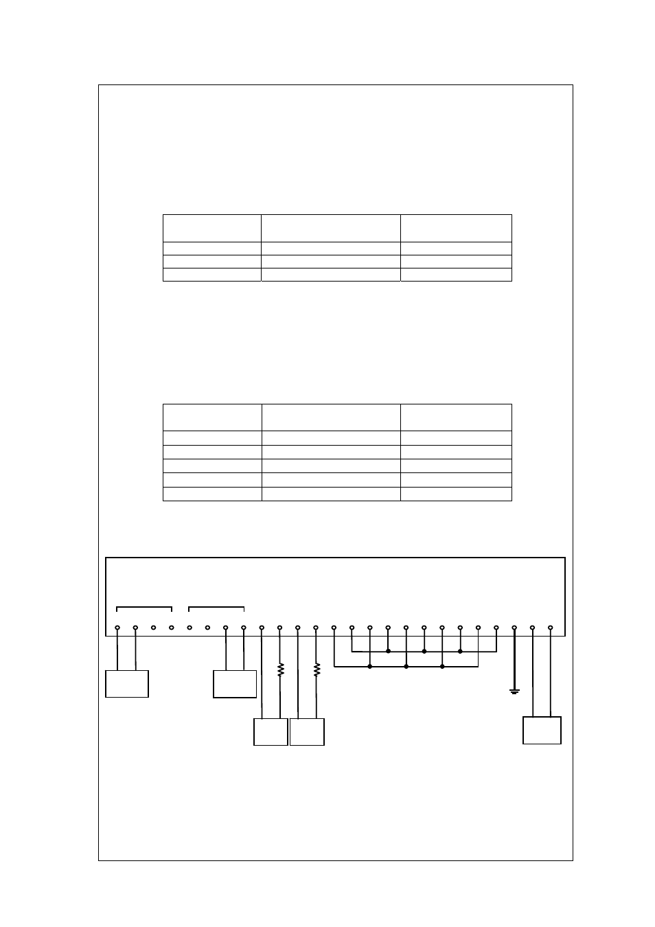
Figure 1 Testing Circuit and Test Equipment
DC402G
11 12 14 15 11 12 14 15 66 65
62
61
22
21
71
72
51
52
41
42 31 32 3 2
1
+
-
+
-
SENSOR 1
SENSOR 2
mA2 mA1
Decade
Resistance
Box 1
Decade
Resistance
Box 2
Power
Supply
-
+
300
DC
Ammeter
-
+
300
DC
Ammeter