8. other sensor systems, 8. other sensor systems -9 – Yokogawa EXA DC402 Dual-Channel Conductivity Analyzer User Manual
Page 20
IM 12D08E02-01E
Installation and wiring 3-9
3-8. Other sensor systems
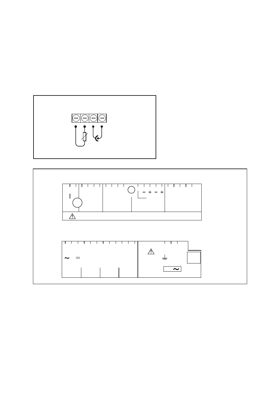
To connect other sensor systems, follow the general pattern of the terminal connections as listed below:
11 and 12
Always used for temperature compensation resistor input (Pt1000, Ni100, Pt100, PB36
and 8k55)
14
Normally used for the outer electrode
15
Used for inner electrode
In case a 4-electrode measuring system will be used, 14 and 16 should be used for the current elec-
trodes.Please ensure that shielded cabling will be used.
In figure 3-10 this is shown in a schematic way.
Figure 3-10. Connection diagram for other sensors
Figure 3-11. Terminal identification labels example
t
11 12
TEMPERATURE
SENSOR
CELL
ELECTRODE
14 15
2-electrode configuration
23
SCREEN
mA1
DC402 REFER TO INSTRUCTION MANUAL FOR CONNECTIONS
mA2
SCREEN
mA OUTPUT
CONT
SENSOR 1
22 21 11 12 14 15 11 12
63 66 65 62 61 95 94 93 92 91
14 15
SENSOR 2
S1
NO
NC
C
S2
NO
NC
C
S3
NO
NC
C
1
2
3
33
32
31
43
42
41
53
52
51
73
72
71
S4
NO
NC
C
L
N
G
FUSE
250V
T200mA
115 VAC
250VAC
5A
100VA
250VDC
5A
50W
Sensor Inputs
Relay Contacts
Power Supply
mA Outputs