Yokogawa EXA DC402 Dual-Channel Conductivity Analyzer User Manual
Page 48
IM 12D08E02-01E
Parameter setting 5-23
100
50
0
0.3 s
% controller output
Code Display
Function
Function detail
X
Y
Z
Default values
Contacts (continued)
44
*D.TIME
Delay time
Minimum relay switching time
0.2 sec.
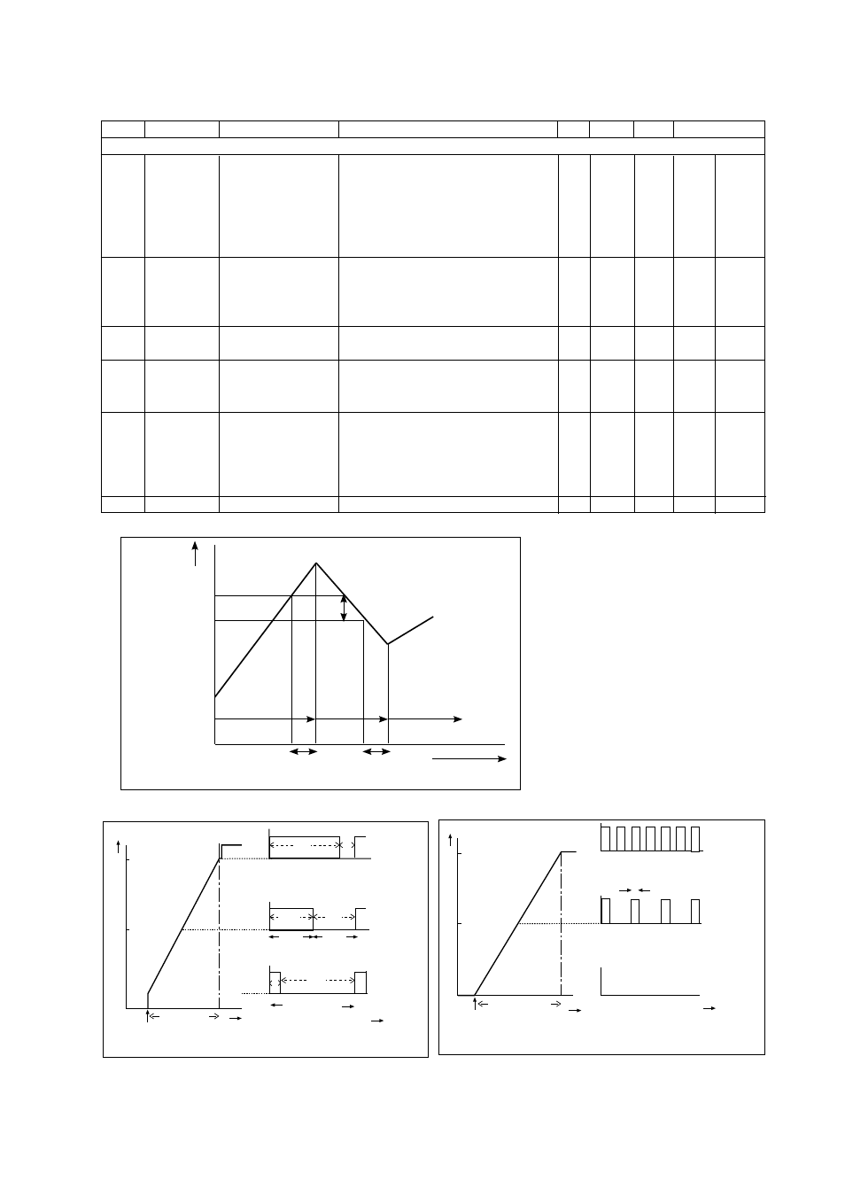
*SC.HYS
Process hysteresis
Minimum change of process value
2.0 %
for relay reset after switching
*T.HYST
Hysteresis temp.
Minimum temperature change for relay
1 °C
reset after switching (fig. 5-3)
*C.HYST
Calculation hysteresis
0
45
*RANGE
Proportional range
When proportional control selected
10.0 %
in code 40, 41, 42 or 43
*PER.
Duty cycle period
Pulse control On time + Off time (fig. 5-4)
10 sec.
*FREQ.
Maximum frequency 100% value for frequency control (fig. 5-5)
70 p/m
46
*tI.CNT
Integral time
Integral time for relay controls when
100 sec.
PI is set
47
*EXPIR
Expiry time
Warning of ineffective control action On
1
0
Off
Warning of ineffective control action Off
0
*tE.min
Set expiry time
Set expiring time using >, ^, ENT keys
15 min
48
*SC1
Set control range
Set range for *SC1 (*SC2) for proportional
contact control when *SC1 (*SC2) are not
used on mA1 (mA2)
0%
Set begin scale
Use >,^, ENT keys to set value
*100%
Set end scale
Use >, ^ ENT keys to set value
49
Not used
90%
100
50
0
on
t
t
of f
90%
10%
50%
50%
10
%
Fig. 5-4. Duty cycle control
SC
% of output range
% duty cycle control
Setpoint
Proportional
range
Time
Pulse period
Fig. 5-5. Pulse frequency control
SC
% of output range
Setpoint
Proportional
range
Time
Maximum pulse frequency
50 % pulse frequency
No pulses
Fig. 5-3.
t (sec)
LED off
Setpoint
LED on
Delay time
Delay time
LED off
Cond./Resist.
Hys.