2. preparation, 2. preparation -4, Warning – Yokogawa EXA DC402 Dual-Channel Conductivity Analyzer User Manual
Page 15
IM 12D08E02-01E
3-4 Installation and wiring
3-2. Preparation
Refer to figure 3-4. The relay contact terminals and power supply connections are under the screening
(shielding) plate. These should be connected first. Connect the sensor and outputs.
To open the EXA 402 for wiring:
1. Loosen the four frontplate screws and remove the cover.
2. Use the rubber knob in the lower righthand corner and swing open the display board to the left.
3. The upper terminal strip is now visible.
4. Remove the screen (shield) plate covering the lower terminal strip.
5. Connect the power supply and contact outputs. Use the three glands at the back for these cables.
6. Replace the screen (shield) plate over the lower terminals.
Always replace the screen plate over the power and contact outputs for safety and avoid
interference.
7. Connect the analog output(s) and the sensor input.
8. Use the front three glands for analog output, sensor input, contact input and communication cabling
(see figure 3-5).
9. Close the display board and switch on the power. Commission the instrument as required or use the
default settings.
10. Replace the cover and secure frontplate with the four screws.
Tighten four frontplate screws to 1.5 N·m torque.
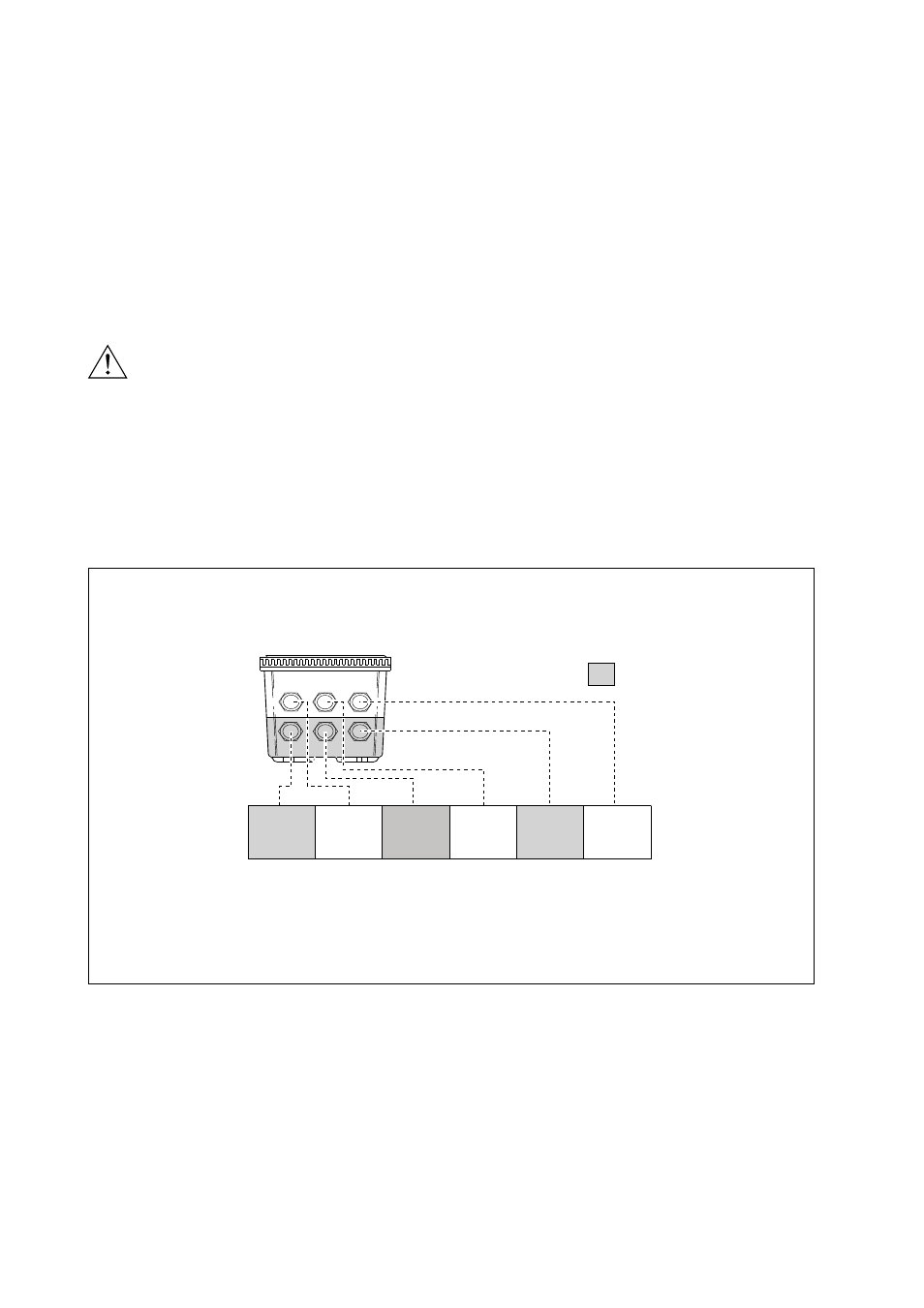
Figure 3-5. Glands to be used for cabling
WARNING
Suitable for cables with an outside diameter between 6 - 12 mm (0.24 - 0.47 in.)
Contact
(S3,S4,FAIL)
output cables
Sensor
cables
Contact
(S1,S2)
output cables
Sensor
cables
Power
cable
Analog
output cable
High voltage section