3. wiring the power supply, 3-1. general precautions, 3-2. access to terminal and cable entry – Yokogawa EXA DC402 Dual-Channel Conductivity Analyzer User Manual
Page 16: 3. wiring the power supply -5, 3-1. general precautions -5, 3-2. access to terminal and cable entry -5
IM 12D08E02-01E
Installation and wiring 3-5
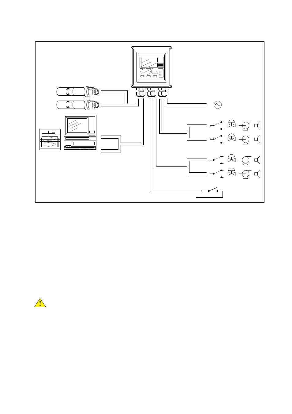
FRONT GLANDS
REAR GLANDS
Sensors
0/4-20 mA Output
signals
Contact
output
Contact
output
Contact
input
0/4-20 mA
Power
S1
S2
S3
S4/FAIL
Figure 3-6. System configuration
3-3. Wiring the power supply
3-3-1. General precautions
Make sure the power supply is switched off. Also, make sure that the power supply is correct for the
specifications of the EXA and that the supply agrees with the voltage specified on the nameplate.
Remove the front cover by unscrewing the four screws to check this nameplate on the top of the display
board.
Local health and safety regulations may require an external circuit breaker to be installed. The instru-
ment is protected internally by a fuse. The fuse rating is dependent on the supply to the instrument. The
250 VAC fuses should be of the “time-lag” type, conforming to IEC60127.
The internal fuse is located next to the power terminals (in the lower right hand corner).
Use only a fuse of the specified current, voltage and type ratings to prevent fire. For fuse replacement,
refer to Section 7-3, “Fuse Replacement.”
3-3-2. Access to terminal and cable entry
Terminals 1 and 2 on the bottom terminal strip are used for the power supply. Guide the power cables
through the gland closest to the power supply terminals. The terminals will accept wires of 2.5 mm
2
(14
AWG). Use cable finishings if possible.
Connect the wires as indicated in the wiring diagram (refer to figure 3-6).
DANGER