5. calibration settings, 6. impedance setting – Yokogawa EXAxt PH450 4-Wire Analyzer for pH and ORP User Manual
Page 34
26
IM 12B07C05-01E
5-5. Calibration settings
Calibration settings for a pH converter involve
slope (sensitivity), zero (aspot) and ITP (iso
thermal point). The following figure shows
the pH value to the mV output of the sensor.
Characteristic for pH measurement is an offset
also known as aspot [mV] or zero [pH] and a
Slope [mV/pH]. For an ideal sensor the theo-
retical slope is 59.16 mV/pH at 25ºC. Slope can
be entered in mV/pH or a percentage of the
theoretical slope (100% corresponds to 59.16
mV/pH). ITP is where the output of the sensor
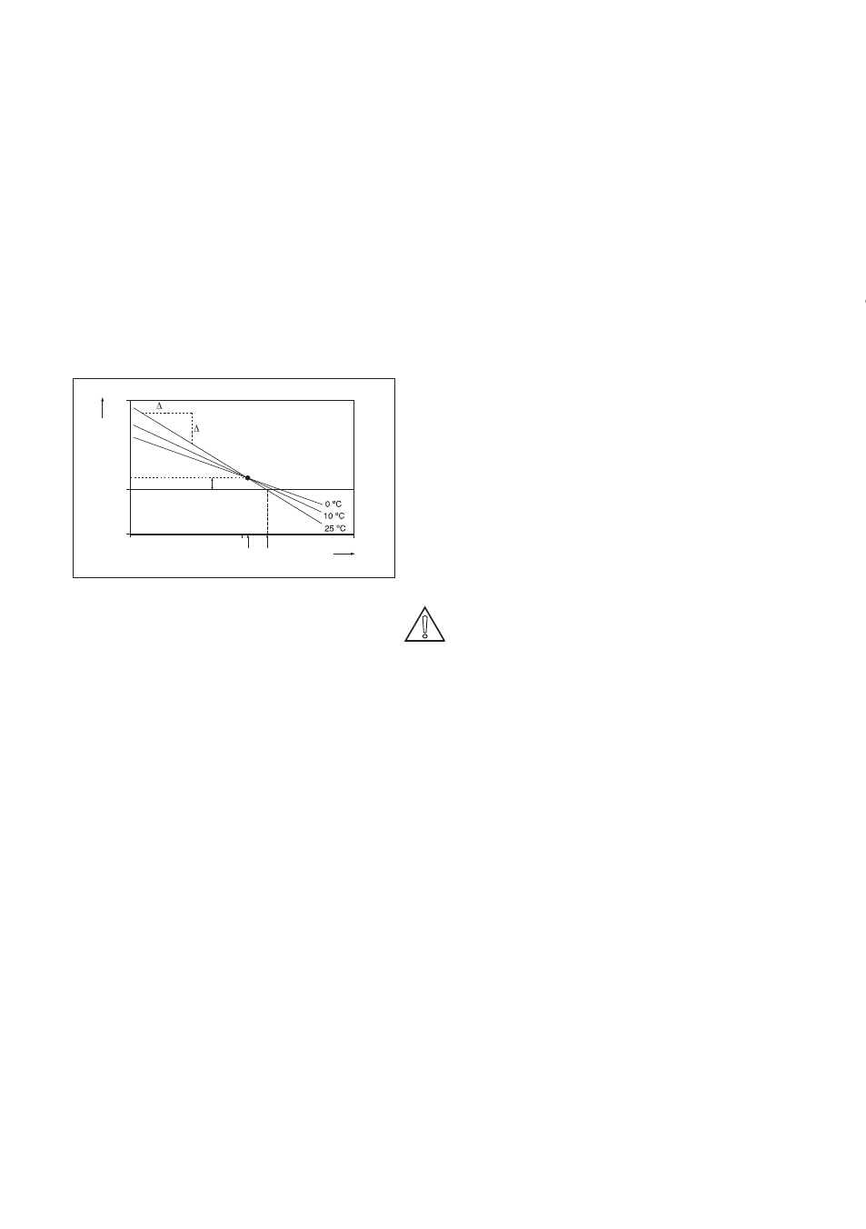
does not change with temperature. Note that
slope and zero are defined at 25ºC.
pH
mV
ITP
As pot
0 mV
mV
500
0
- 200
14
pH
ITP Zero
0
7
Figure 5-1. Calibration parameters
Units
Zero (aspot) unit. Zero is an alternative to
Asymmetry Potential. This method conforms to
the DIN standard for instruments IEC 60146-2.
Zero is defined in pH or mV.
Slope (sensitivity) unit
Slope can be defined in mV/pH or defined as
percentage of theoretical slope at 25ºC.
Limits and timing
Zero (aspot) High, Low. During calibration the
new zero is checked for exceeding these low
and high limits. Narrowing the band will prevent
bad calibration procedures and calibration of
bad sensors, which results in higher accuracy.
The default values should be adjusted to suit
the application and the “users” criterion.
Slope (sensitivity) high, low
During calibration the new slope is checked for
exceeding these low and high limits. Narrowing the
band will prevent bad calibration procedures and
calibration of bad sensors, which results in higher
accuracy. The default values should be adjusted to
suit the application and the “users” criterion.
Stabilization time
During calibration, the value should be stable
within 0.01 pH over this stabilization time pe-
riod. When the pH value is not stable within 10
minutes, calibration is aborted.
Calibration interval
The interval in which a new calibration must
take place. If the interval is exceeded the
instrument will give a warning or a fail (user
definable in error configuration 2/3)
Buffers
Calibration is done using standard calibration
buffers. Our preference goes to NIST buffers
for highest accuracy, but the user is free to
select US, DIN or define his own. The standard
buffers can be found in Appendix 1.
Zero (aspot)/slope (sensitivity)/ITP
Zero (aspot), Slope (sensitivity), ITP values can
be entered directly in this section. These data can
be provided by the manufacturer of the probe, or
by the users laboratory etc. They are determined
independently of the measuring loop.
Note! it is not necessary to enter this data. In
most cases as the EXAxt automatically
does this while performing a calibration.
The feature is used in the case of special
electrode systems and where calibration
in the process environment is not
possible. See chapter 6.
5-6. Impedance setting
Reference impedance High, Low. The EXAxt
has an impedance check, capable of moni-
toring the impedance of all sorts of sensor
systems. In order to “fine tune” this diagnostic
tool it is necessary to set it up to match the
sensors used.
The system is set to measure the impedance of
Glass (high) and reference (low) electrodes.
In applications that have a tendency to leave
deposits on the electrodes and to clog the
reference sensor junction there is the possibility
to use the impedance check (set error configu-
ration) on the reference sensor to initiate an
alarm, or to initiate the wash cleaning process,
when one of the limits is exceeded.