6. wiring the sensor system, 6-1. impedance measurement jumper settings – Yokogawa EXAxt PH450 4-Wire Analyzer for pH and ORP User Manual
Page 20
12
IM 12B07C05-01E
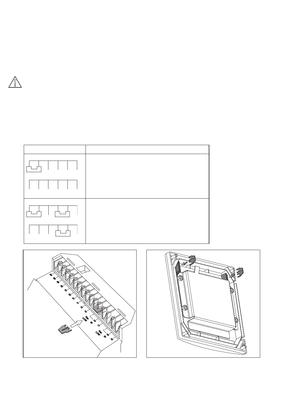
Table 3-1. Impedance measuring jumpers
Jumper Settings
Application & Sensor Connections
16
13 17
15
Normal pH sensors (including FU20).
Glass sensor on Input 1.
Reference sensor on Input 2.
Special electrodes using 2 glass sensors.
(e.g. Pfaudler)
ORP (Redox measurement).
Metal sensor on Input 1.
Normal reference on Input 2.
ORP (pH compensated) or rH measurement
Metal sensor on Input 1.
pH glass (as reference) on Input 2.
63
66
65
62
61
22
21
11
12
14
IN
Imp.
LOW
IN
13
17
15
16
Imp.
LOW
Figure 3-9a. Jumper placement for low
impedance setting
Figure 3-9b. Jumper holders in cover
3-6. Wiring the sensor system
3-6-1. Impedance measurement jumper settings
Impedance measurement is a powerful
diagnostic tool. In order to perform impedance
measurements it is important to have a good
jumper setting. The table and figure below will
guide you to make the right setting.
Note! It is important to decide first which
application and which settings are
appropriate for the installation. This
decision is best done before the
jumpers are installed, because the
cables will rest on top of the jumpers in
their installed positions.
Figure 3-9a. shows the jumper positions related
to the types of measurement stated in Table
3-1.
For Low impedance the Low should be shorted
by a jumper. See drawing below.
When shipped, two jumpers are placed in a
plastic bag and supplied with the product. Typi-
cal setting for pH measurement, 13 is shorted
to become a low impedance input. Unused
jumpers should be stored in jumper holders in
the cover, as shown in Figure 3-9b.