3-4. slope – Yokogawa EXAxt PH450 4-Wire Analyzer for pH and ORP User Manual
Page 28
20
IM 12B07C05-01E
of the sensor (default 7.00 pH). The ZERO
value indicates the condition of the sensor. If
the value exceeds +/- 120 mV (or user defined
limits) an error message is displayed after
calibration and the calibration is rejected. The
trend of ZERO drift during the lifetime of the
sensor is used to predict the lifetime of the
sensor.
ZERO can also be displayed in pH units and
then it represents the pH value where the
sensor output is 0 mV at 25 ºC. Go to:
Com-
missioning >> Measurement >> Calibration
Settings >> Zero and Slope Units
4-3-4. Slope
= calibrated efficiency of the sensor unit in
percentage of theoretical slope of the sensor
unit. The theoretical slope follows the NERNST
equation and is 59.16 mV/pH. The SLOPE can
be calibrated only after a two-point calibration
in buffer solutions with a different pH value. A
low slope indicates that the sensor is not clean
or it indicates a bad sensor. If the calibrated
slope exceeds the range 70-110% (or user
defined limits) then the calibration is rejected
and a error message is shown.
The SLOPE can also be displayed as mV/pH
value at 25 ºC if the user has defined this
variable as mV/pH in
Commissioning >>
Measurement >> Calibration Settings >>
Zero and Slope Units
4-3-5. Sensor mV
= the output of the sensor unit prior to calibra-
tion and temperature compensation. This value
is important for trouble shooting.
4-3-6. Reference impedance
= the electrical resistance of the liquid junc-
tion. The liquid junction forms the electolytical
contact between the reference element and
the measuring electrode, so it must be kept
clean and filled with conductive electrolyte.
Otherwise the measurement will suffer from
instability, drift and measuring errors. The elec-
trical impedance is one of the most important
diagnostic tools for keeping the measurement
in good condition. If the value exceeds a user
defined limit (1000Ω - 1000kΩ) an error mes-
sage will be displayed.
4-3-7. Last calibrated
= the date on which the last sensor calibra-
tion is done. The displayed value of the ZERO
is the result of this calibration. The displayed
value of Slope is not necessarily calibrated
on this date: only if the last calibration was a
2-point calibration.
4-3-8. Calibration due
= the date when the calibration must be done
according to the settings of the maintenance
timer. This is based on scheduled maintenance
procedures. The maintenance intervals are
set in menu:
setup>> Commissioning>>
measurement setup>> calibration settings
>> limits and timing
4-3-9. Projected calibration
= the date when the predictive maintenance
function expects that recalibration of the sen-
sor unit is necessary for good measurement
accuracy. The converter checks the reference
impedance every hour. The user is notified
when maintenance should take place. Prior to
calibration the sensor should be well cleaned
and rinsed.
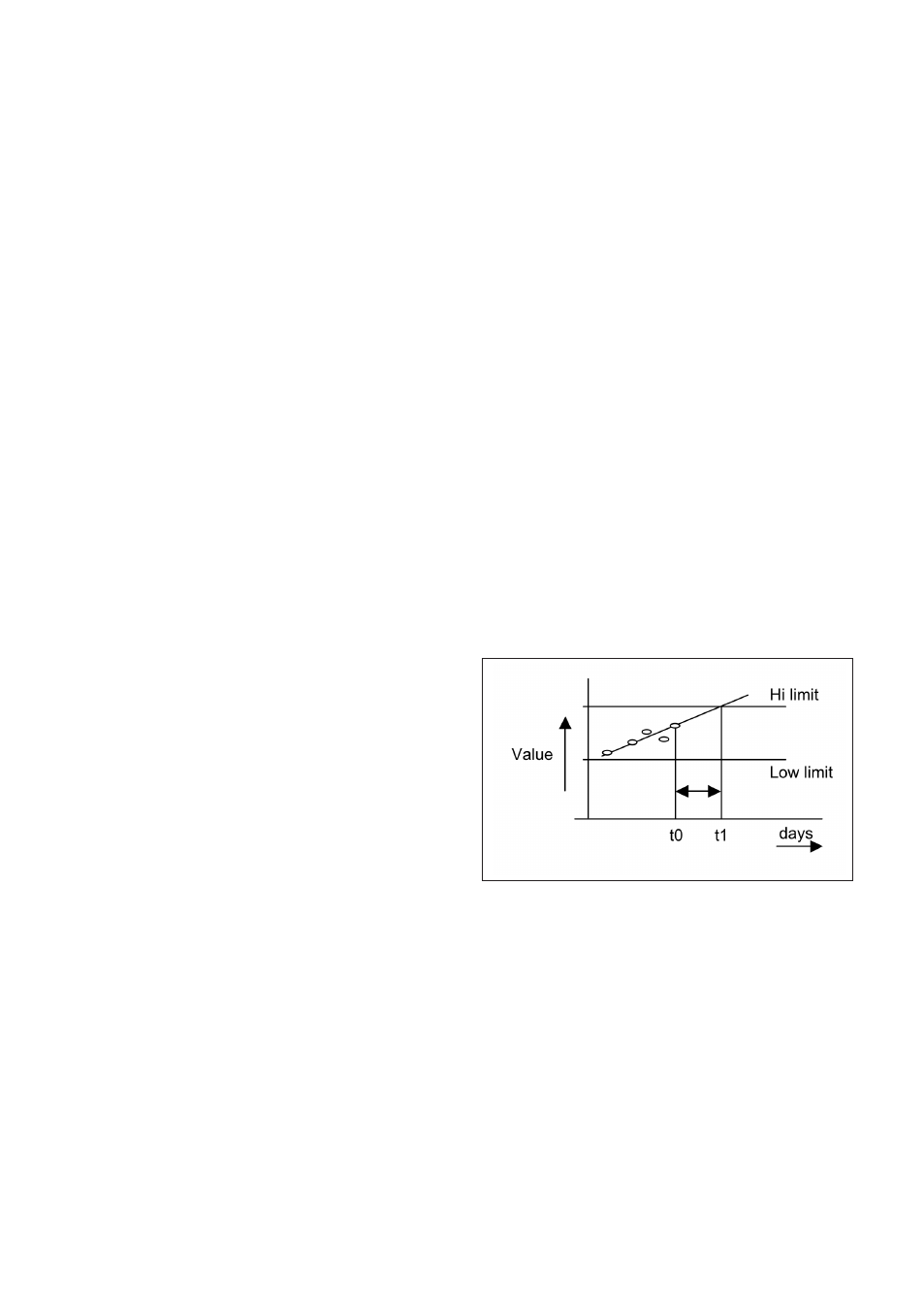
4-3-10. Projected replacement
= the date when the predictive maintenance
function expects that replacement of the
sensor is necessary for good measurement
accuracy. After each calibration the slope, zero
and reference impedance are logged. Aging
of the sensor can be detected from this data.
The observed trend is extrapolated and the
trend predicts when max deviations will be
exceeded. Good predictions are only achieved
with good calibration data. Prior to calibration
the sensor should always be well cleaned and
rinsed and the calibration procedures strictly
observed.