3-5. grounding the housing, 3-6. switching on the instrument, Warning – Yokogawa EXAxt PH450 4-Wire Analyzer for pH and ORP User Manual
Page 18: Danger, Power
10
IM 12B07C05-01E
3-3-5. Grounding the housing
For the safety of the user and to protect the
instrument against interference, the housing
must always be connected to ground. This has
to be done by a large area conductor. This
cable can be fixed to the rear of the housing or
by using the internal ground connections using
a braided wire cable. See figure 3-8.
The minimum cross sectional area of the pro-
tective grounding wire should be 0.75 mm
2
.
3-3-6. Switching on the instrument
After all connections are made and checked,
the power can be switched on from the power
supply. Make sure the LCD display comes on.
After a brief interval, the display will change to
the measured value. If errors are displayed or
a valid measured value is not shown, consult
the troubleshooting section (Chapter 8) before
calling Yokogawa.
DANGER
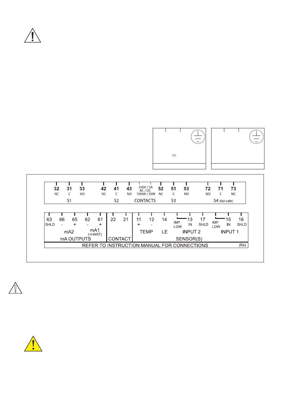
Figure 3-7. Input and output connections
2
1
-
+
DC
POWER
12-24 V /10 W
FUSE: 2A/250 VAC/T
2
1
N
L
AC
POWER
100-240 VAC/15 VA/ 50/60Hz
FUSE: 500 mA/250 VAC/T
Fuse replacement should be performed only by
a qualified service personnel.
See Sec.7. MAINTENANCE, Fuse.
Fuse ratings:
Power supply
Fuse type
12-24 VDC, 10W max
2A/250V, Slow
100-240 VAC, 15VA max 0.5A/250V, Slow
3-3-2. Access to terminal and cable entry
Terminals 1 and 2 are used for the power sup-
ply. Guide the power cables through the gland
closed to the power supply terminals. The ter-
minals will accept wires of 2.5 mm
2
(14 AWG).
Always use cable finishings if possible.
WARNING
3-3-3. AC power
Connect terminal L to the phase line of the AC
power and terminal N to the zero line. See fig-
ure 3-8 for the power ground. This is separated
from input ground by a galvanic isolation.
3-3-4. DC power
Connect terminal 1 to the positive outlet and
terminal 2 to the negative outlet.
This is separated from input ground by a
galvanic isolation. The size of conductors
should be at least 1.25 mm
2
. The overall cable
diameter should be between 6 & 12 mm.