3-13. hart device revision, 3-14. logbook, 4. information function – Yokogawa EXAxt PH450 4-Wire Analyzer for pH and ORP User Manual
Page 29: 5. setup-calibration & commissioning, 6. secondary-primary value display switch
21
IM 12B07C05-01E
4
OPERATION
OF
EXAxt
PH450G
4-3-11. HART ID = a part of the HART device ID
(descriptor)
4-3-12. Software revision = the revision level of
the software in the instrument
TROUBLE SHOOTING
If you contact the local sales/ service organiza-
tion the serial number and software revision is
necessary information. Without that information
it is impossible to help you. It is also very useful
to report all the information that you find on the
zoom-in display.
4-3-13. HART Device revision
Sometimes the firmware of a device is
updated in a way that the communication file
(HART DD) need revision too. In this case the
revision level is increased by one. The revision
level of the HART DD must match the revision
level of the Firmware. The revision level is
expressed by the first two characters of the
filename.
The following files should be used when the
HART Device revision level is 2.
(0201.aot, 0201.fms, 0201.imp, 0201.sym)
4-3-14. Logbook
The EXAxt contains several logbooks to store
history information on events, changed settings
and calibrations. The logbooks have been
categorized to simplify the retrieval of this
information.
Calibration will give information of previous
calibrations. This logbook is useful as one now
can
1) Monitor the sensor performance over time.
2) Monitor the sensor(s) lifetime.
Sensor will give all history information on
parameter settings concerning the sensor(s).
The events logged in this logbook are user
definable. This is done in
Commissioning >>
Configure Logbook >> Sensor Logbook.
Predictive maintenance. If the sensor diag-
nostics of the EXAxt are enabled, the diagnos-
tics are saved into this logbook.
For the EXAxt PH450G, the reference imped-
ance (measured between the Liquid earth and
the reference electrode) is stored every hour.
This information can be used for (predictive)
maintenance schedules as the impedance is a
measure of fouling and the sensor should be
kept clean for best results.
Settings will give all history information on pa-
rameter settings concerning the analog outputs
(mA1/mA2) and contact (S1…S4). This logbook
is useful to trace back differences in perform-
ance due to changed settings. The events
logged in this logbook are user definable. This
is done in
Commissioning >> Configure
Logbook >> Settings Logbook – mA and/or
Settings Logbook – contact
mA1/mA2 shows all (dynamic) events concern-
ing the analog outputs
S1/S2/S3/S4 shows all (dynamic) events con-
cerning the contacts.
Each HMI screen can contain up to 5 events.
As the logbook can contain 50, one can access
previous events by selecting events page 1 to
10.
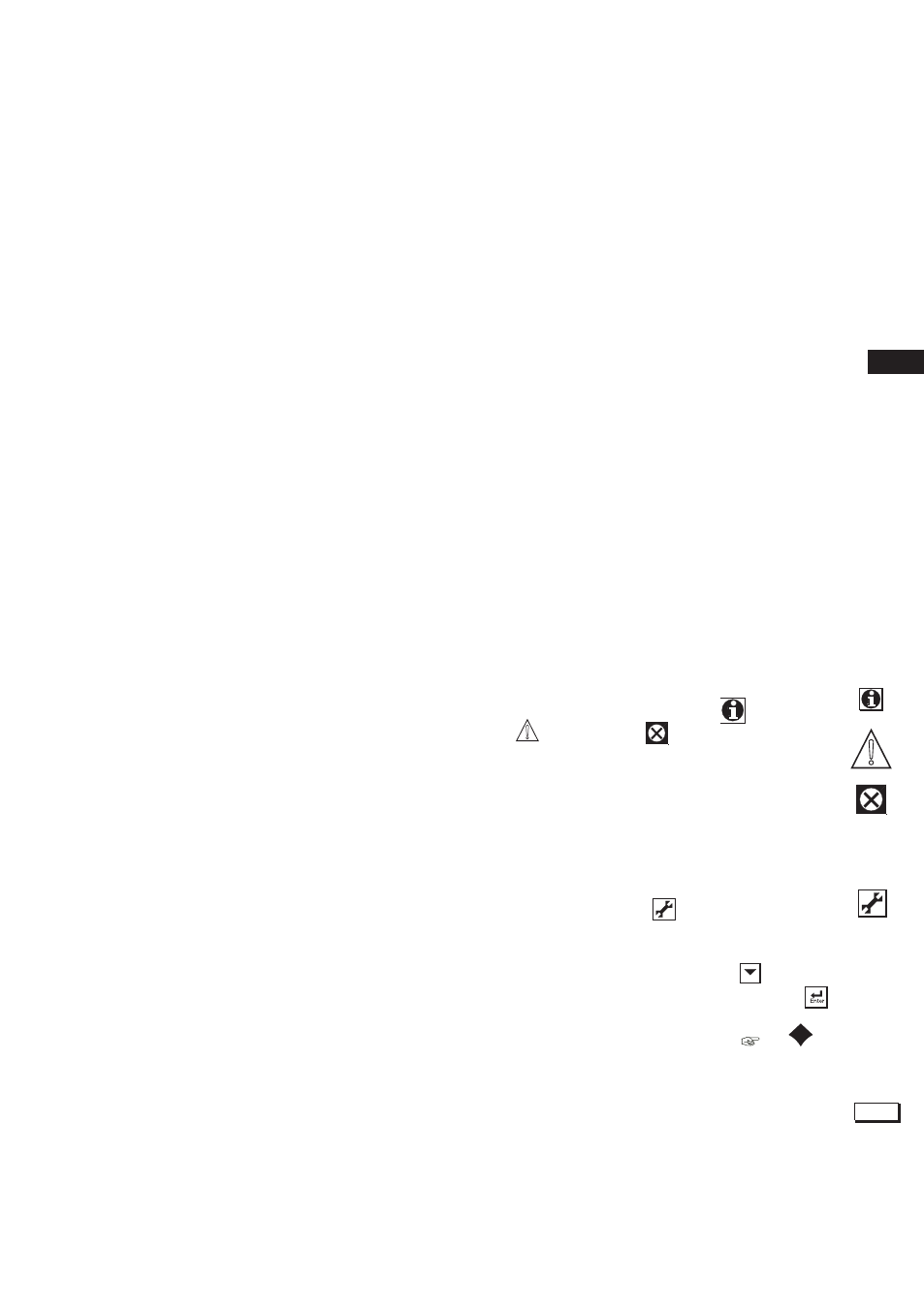
4-4. Information function
In this field an information sign
, a warning
sign
or a fail sign
can appear. Pushing
this button, the user gets detailed information
about the status of the sensor or the instrument
if applicable.
See troubleshooting (chapter 8) for further
details.
4-5. Setup-calibration & commissioning
By pressing the setup
key, you get access
to the operating system of the converter based
on menus and submenus.
Browse through the list using the
key till
you find the required menu and press the
key to enter this menu.
It is also possible to press on the
or
symbol found beside the menu item.
4-6. Secondary-primary value display switch
Pressing on this text block automatically
switches the secondary value to the main
display (Large font size).
25.0