Process flange size: 4 inch (100 mm), Process flange size: 3 inch (80 mm), Process flange size: 2 inch (50 mm) – Yokogawa EJX118A User Manual
Page 61
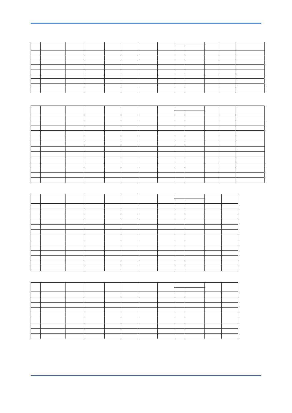
<8. General Specifications>
8-19
IM 01C25H01-01E
Unit: mm (Approx.: inch)
Process flange size: 4 inch (100 mm)
Code Flange rating
øD
øC
øg
ød
t
f*3*4
Bolt holes
j
k
øA
No.(n)
Dia.(øh)
J1 JIS 10K
210(8.27)
175(6.89) 155(6.10)
—
18(0.71)
0
8
19(0.75)
—
—
96±0.5(3.78±0.02)
J2 JIS 20K
225(8.86)
185(7.28) 155(6.10)
—
24(0.94)
0
8
23(0.91)
—
—
96±0.5(3.78±0.02)
J4 JIS 40K
250(9.84)
205(8.07) 155(6.10)
—
36(1.42)
0
8
25(0.98)
—
—
96±0.5(3.78±0.02)
A1 ANSI class 150 228.6(9.00) 190.5(7.50) 155(6.10)
—
23.9(0.94) 1.6(0.06)
8
19.1(0.75)
—
—
96±0.5(3.78±0.02)
A2 ANSI class 300 254(10.00) 200.2(7.88) 155(6.10)
—
31.8(1.25) 1.6(0.06)
8
22.4(0.88)
—
—
96±0.5(3.78±0.02)
P1 JPI class 150
229(9.02) 190.5(7.50) 155(6.10)
—
24(0.94)
1.6(0.06)
8
19(0.75)
—
—
96±0.5(3.78±0.02)
P2 JPI class 300
254(10.0) 200.2(7.88) 155(6.10)
—
32(1.26)
1.6(0.06)
8
22(0.87)
—
—
96±0.5(3.78±0.02)
D2 DIN PN10/16
220(8.66)
180(7.09) 155(6.10)
—
20(0.79)
0
8
18(0.71)
—
—
96±0.5(3.78±0.02)
D4 DIN PN25/40
235(9.25)
190(7.48) 155(6.10)
—
24(0.94)
0
8
22(0.87)
—
—
96±0.5(3.78±0.02)
Process flange size: 3 inch (80 mm)
Code Flange rating
øD
øC
øg
ød*2
t
f*3*4
Bolt holes
j*1
k
øA
No.(n)
Dia.(øh)
J1 JIS 10K
185(7.28)
150(5.91) 130(5.12) 90(3.54)
18(0.71)
0
8
19(0.75)
25(0.98) 27(1.06) 71±0.5(2.8±0.02)
J2 JIS 20K
200(7.87)
160(6.30) 130(5.12) 90(3.54)
22(0.87)
0
8
23(0.91)
25(0.98) 27(1.06) 71±0.5(2.8±0.02)
J4 JIS 40K
210(8.27)
170(6.69) 130(5.12) 90(3.54)
32(1.26)
0
8
23(0.91)
25(0.98) 27(1.06)
—
J6 JIS 63K
230(9.06)
185(7.28) 130(5.12) 90(3.54)
40(1.57)
0
8
25(0.98)
25(0.98) 27(1.06) 71±0.5(2.8±0.02)
A1 ANSI class 150 190.5(7.50) 152.4(6.00) 130(5.12) 90(3.54) 23.9(0.94) 1.6(0.06)
4
19.1(0.75) 25(0.98) 27(1.06) 71±0.5(2.8±0.02)
A2 ANSI class 300 209.6(8.25) 168.1(6.62) 130(5.12) 90(3.54) 28.5(1.12) 1.6(0.06)
8
22.4(0.88) 25(0.98) 27(1.06) 71±0.5(2.8±0.02)
A4 ANSI class 600 209.6(8.25) 168.1(6.62) 130(5.12) 90(3.54) 38.2(1.50) 6.4(0.25)
8
22.4(0.88) 25(0.98) 27(1.06)
—
P1 JPI class 150
190(7.48) 152.4(6.00) 130(5.12) 90(3.54)
24(0.94)
1.6(0.06)
4
19(0.75)
25(0.98) 27(1.06) 71±0.5(2.8±0.02)
P2 JPI class 300
210(8.27) 168.1(6.61) 130(5.12) 90(3.54) 28.5(1.12) 1.6(0.06)
8
22(0.87)
25(0.98) 27(1.06) 71±0.5(2.8±0.02)
P4 JPI class 600
210(8.27) 168.1(6.61) 130(5.12) 90(3.54) 38.4(1.51) 6.4(0.25)
8
22(0.87)
25(0.98) 27(1.06)
—
D2 DIN PN10/16
200(7.87)
160(6.30) 130(5.12) 90(3.54)
20(0.79)
0
8
18(0.71)
25(0.98) 27(1.06) 71±0.5(2.8±0.02)
D4 DIN PN25/40
200(7.87)
160(6.30) 130(5.12) 90(3.54)
24(0.94)
0
8
18(0.71)
25(0.98) 27(1.06) 71±0.5(2.8±0.02)
D5 DIN PN64
215(8.46)
170(6.69) 130(5.12) 90(3.54)
28(1.10)
0
8
22(0.87)
25(0.98) 27(1.06)
—
Process flange size: 2 inch (50 mm)
Code Flange rating
øD
øC
øg
ød*2
t
f*3*4
Bolt holes
j*1
k
No.(n)
Dia.(øh)
J1 JIS 10K
155(6.10)
120(4.72) 100(3.94) 61(2.40)
16(0.63)
0
4
19(0.75)
25(0.98) 27(1.06)
J2 JIS 20K
155(6.10)
120(4.72) 100(3.94) 61(2.40)
18(0.71)
0
8
19(0.75)
25(0.98) 27(1.06)
J4 JIS 40K
165(6.50)
130(5.12) 100(3.94) 61(2.40)
26(1.02)
0
8
19(0.75)
25(0.98) 27(1.06)
J6 JIS 63K
185(7.28)
145(5.71) 100(3.94) 61(2.40)
34(1.34)
0
8
23(0.91)
25(0.98) 27(1.06)
A1 ANSI class 150 152.4(6.00) 120.7(4.75) 100(3.94) 61(2.40) 19.1(0.75) 1.6(0.06)
4
19.1(0.75) 25(0.98) 27(1.06)
A2 ANSI class 300 165.1(6.50) 127.0(5.00) 100(3.94) 61(2.40) 22.4(0.88) 1.6(0.06)
8
19.1(0.75) 25(0.98) 27(1.06)
A4 ANSI class 600 165.1(6.50) 127.0(5.00) 100(3.94) 61(2.40) 31.8(1.25) 6.4(0.25)
8
19.1(0.75) 25(0.98) 27(1.06)
P1 JPI class 150
152(5.98) 120.6(4.75) 100(3.94) 61(2.40) 19.5(0.77) 1.6(0.06)
4
19(0.75)
25(0.98) 27(1.06)
P2 JPI class 300
165(6.50) 127.0(5.00) 100(3.94) 61(2.40) 22.4(0.88) 1.6(0.06)
8
19(0.75)
25(0.98) 27(1.06)
P4 JPI class 600
165(6.50) 127.0(5.00) 100(3.94) 61(2.40) 31.9(1.26) 6.4(0.25)
8
19(0.75)
25(0.98) 27(1.06)
D2 DIN PN10/16
165(6.50)
125(4.92) 100(3.94) 61(2.40)
18(0.71)
0
4
18(0.71)
25(0.98) 27(1.06)
D4 DIN PN25/40
165(6.50)
125(4.92) 100(3.94) 61(2.40)
20(0.79)
0
4
18(0.71)
25(0.98) 27(1.06)
D5 DIN PN64
180(7.09)
135(5.31) 100(3.94) 61(2.40)
26(1.02)
0
4
22(0.87)
25(0.98) 27(1.06)
Process flange size: 1 1/2 inch (40 mm)
Code Flange rating
øD
øC
øg
ød*2
t
f*3*4
Bolt holes
j
k
No.(n)
Dia.(øh)
J1 JIS 10K
140(5.51)
105(4.13)
86(3.39) 44(1.73)
16(0.63)
0
4
19(0.75)
27(1.06) 30(1.18)
J2 JIS 20K
140(5.51)
105(4.13)
86(3.39) 44(1.73)
18(0.71)
0
4
19(0.75)
27(1.06) 30(1.18)
J4 JIS 40K
160(6.30)
120(4.72)
86(3.39) 44(1.73)
24(0.94)
0
4
23(0.91)
27(1.06) 30(1.18)
A1 ANSI class 150 127(5.00) 98.4(3.88) 86(3.39) 44(1.73) 17.5(0.69) 1.6(0.06)
4
15.9(0.63) 27(1.06) 30(1.18)
A2 ANSI class 300 155.4(6.12) 114.3(4.50) 86(3.39) 44(1.73) 20.6(0.81) 1.6(0.06)
4
22.4(0.88) 27(1.06) 30(1.18)
A4 ANSI class 600 155.4(6.12) 114.3(4.50) 86(3.39) 44(1.73) 28.8(1.13) 6.4(0.25)
4
22.4(0.88) 27(1.06) 30(1.18)
P1 JPI class 150
127(5.00)
98.6(3.88) 86(3.39) 44(1.73) 17.6(0.69) 1.6(0.06)
4
16(0.63)
27(1.06) 30(1.18)
P2 JPI class 300
155(6.10) 114.3(4.50) 86(3.39) 44(1.73) 20.6(0.81) 1.6(0.06)
4
22(0.87)
27(1.06) 30(1.18)
P4 JPI class 600
155(6.10) 114.3(4.50) 86(3.39) 44(1.73) 28.9(1.14) 6.4(0.25)
4
22(0.87)
27(1.06) 30(1.18)
*1:
When wetted parts material code UW (titanium) is selected, value is 34 (1.34.)
*2:
Indicates inside diameter of gasket contact surface.
*3:
In case where process flange material is JIS S25C, value of f is 0.
*4:
In case where process flange material is JIS SUS304 in ANSI/JPI flange, value of f is included in t.