5 affixing the teflon film, 6 rotating transmitter section, 7 changing integral indicator direction – Yokogawa EJX118A User Manual
Page 27: Affixing the teflon film -5, Rotating transmitter section -5, Changing integral indicator direction -5, Important, 7 changing integral indicator direction important
<4. Installation>
4-5
IM 01C25H01-01E
4.5 Affixing the Teflon Film
The FEP Teflon option includes a teflon film and
fluorinated oil.
Before mounting the diaphragm seal to the process
flange, affix the teflon film as follows:
IMPORTANT
1) Position the diaphragm seal so that the
diaphragm is in a upward position.
2) Pour the fluorinated oil on the diaphragm
and gasket area covering it completely
and evenly. Be careful not to scratch the
diaphragm or change the its shape.
3) Affix the teflon film over the diaphragm and
gasket area.
4) Next, carefully inspect the cover and try
to identify any entrapped air between
the diaphragm and the teflon film. The
air must be removed to ensure optimum
performance. If air pockets are present, use
your fingers to remove the air by starting at
the center of the diaphragm and work your
way out.
5) Position the gasket on the Teflon film.
6) Mount the transmitter onto the process
flange.
Teflon film
Diaphragm
Fluorinated oil
[PART No.: F9145YN]
Gasket area
Diaphragm seal
PART No.
F9347XA
F9347YA
Process flange size
For 3inch (80 mm)
For 2inch (50 mm)
F0408.ai
Figure 4.8
Affixing the Teflon Film
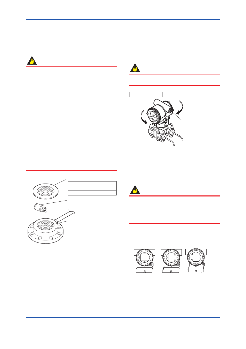
4.6 Rotating Transmitter Section
The transmitter section can be rotated in either
direction to any desired position. Note that there is
a stopper which prevents the transmitter from being
rotated more than 360°.
(1) Using the Allen wrench, remove the two
setscrews securing the transmitter section to
the capsule assembly.
(2) Rotate the transmitter section slowly to the
desired position.
(3) Tighten the two setscrews to a torque of 1.5
N·m {15 kgf·cm}.
IMPORTANT
Do not rotate the transmitter section more than
the above limit.
F0409.ai
Rotate 180° segments
Transmitter section
Pressure-detector section
Conduit connection
Figure 4.9
Rotating Transmitter Section
4.7 Changing Integral Indicator
Direction
IMPORTANT
• Always turn OFF power and shut off and
release pressures before disassembly.
• For changing the integral indicator direction,
the transmitter must be removed to a non-
hazardous area.
An integral indicator can be installed in the following
three directions, Refer to subsection 7.4 for
attaching and removing the integral indicator.
F0410.ai
Figure 4.10 Integral Indicator Direction