2 replacing the cpu board assembly, 5 troubleshooting, 1 basic troubleshooting – Yokogawa EJX118A User Manual
Page 39: Replacing the cpu board assembly -4, Troubleshooting -4 7.5.1, Basic troubleshooting -4
<8. Maintenance>
7-4
IM 01C25H01-01E
F0703.ai
Press
forward
Output terminal cable
Zero-adjustment
screw pin
Slide
switch
Boss
Zero-
adjustment
screw
Integral
indicator
Mounting screw
Amplifier Cover
CPU assembly
Bracket
(for zero-adjustment
screw pin)
LCD board assembly
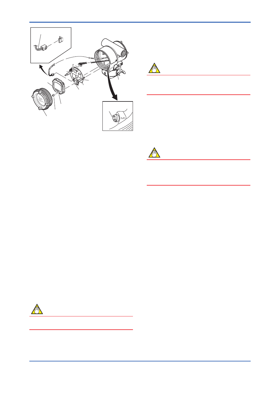
Figure 7.3
Removing and Attaching LCD Board
Assembly and CPU Assembly
7.4.2 Replacing the CPU Board Assembly
This subsection describes the procedure for
replacing the CPU assembly. (See figure 7.3)
■ Removing the CPU Assembly
1) Remove the cover. If an integral indicator is
mounted, refer to subsection 7.4.1 and remove
the indicator.
2) Turn the zero-adjustment screw to the position
(where the screw head slot is horizontal) as
shown in figure 7.3.
3) Disconnect the output terminal cable (cable
with brown connector at the end). When doing
this, lightly press the side of the CPU assembly
connector and pull the cable connector to
disengage.
4) Use a socket driver (width across flats, 5.5mm)
to loosen the two bosses.
5) Carefully pull the CPU assembly straight
forward to remove it.
6) Disconnect the flat cable (cable with white
connector at the end) that connects the CPU
assembly and the capsule.
NOTE
Be careful not to apply excessive force to the
CPU assembly when removing it.
■ Mounting the CPU Assembly
1) Connect the flat cable (with white connector)
between the CPU assembly and the capsule.
2) Connect the output terminal cable (with brown
connector).
NOTE
Make certain that the cables do not get pinched
between the case and the edge of the CPU
assembly.
3) Align and engage the zero-adjustment screw
pin with the groove on the bracket on the CPU
assembly. Then insert the CPU board assembly
straight onto the post in the amplifier case.
4) Tighten the two bosses. If the transmitter is
equipped with an integral indicator, refer to
subsection 7.4.1 to mount the indicator.
NOTE
Confirm that the zero-adjustment screw pin is
placed properly in the groove on the bracket prior
to tightening the two bosses. If it is not, the zero-
adjustment mechanism will be damaged.
5) Replace the cover.
7.5 Troubleshooting
If any abnormality appears in the measured values,
use the troubleshooting flow chart below to isolate
and remedy the problem. Since some problems
have complex causes, these flow charts may
not identify all. If you have difficulty isolating or
correcting a problem, contact Yokogawa service
personnel.
7.5.1 Basic Troubleshooting
First determine whether the process variable
is actually abnormal or a problem exists in the
measurement system.
If the problem is in the measurement system,
isolate the problem and decide what corrective
action to take.