Ac power wiring, Thermocouple input, Rtd input – Watlow Series L Temperature Limit User Manual
Page 9
Wa t l ow S e r i e s L
• 7 • C h a p te r
3 :
Wi r i n g
ç
Warning:
Use National Electric (NEC) or
other country-specifi c standard
wiring and safety practices
when wiring and connect-
ing this controller to a power
source and to electrical sen-
sors or peripheral devices.
Failure to do so may result
in damage to equipment and
property, and/or injury or loss
of life.
Ó
WARNING:
If high voltage is applied to a
low-voltage controller, irrevers-
ible damage will occur.
Note:
Insulated terminals required for
quick connect style terminals.
For quick connect terminals
1, 2, 6, 7, 8, 9, and 10, AMP
P/N 3-520406-2 or equivalent
recommended. Use Amp crimp
tool P/N 58078-3, insert 90391-
3.
For quick connect terminals 3,
4, and 5, AMP P/N 2-520405-2
or equivalent recommended.
Amp crimp tool P/N 58078-3,
insert 58079-3.
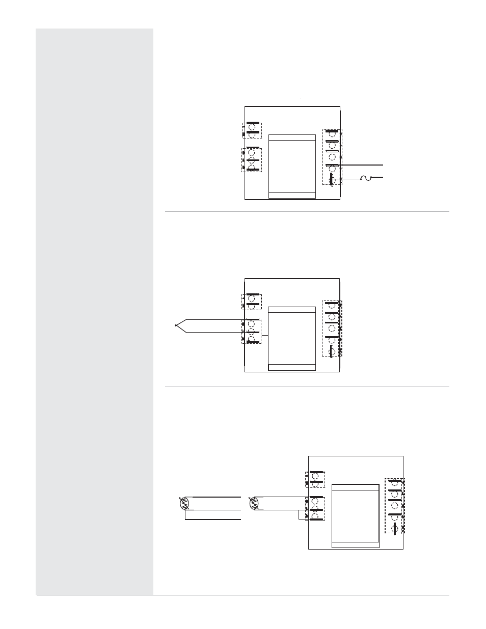
Figure 7a —
AC Power Wiring
• Nominal voltage options:
• 24V
Å (ac)
• 120V
Å (ac)
• 230 to 240V
Å (ac)
L1
L2
1
2
3
4
5
6
10
9
8
7
Figure 7b —
Thermocouple Input
Thermocouples are polarity sensitive. The negative lead (usually red) must be
connected to the negative thermocouple terminal.
• Input impedance: >10 MΩ
Thermocouple
-
Thermocouple +
1
2
3
4
5
6
10
9
8
7
Figure 7c —
RTD Input
(100 Ω Platinum DIN curve 0.00385 Ω/Ω/°C)
• Terminals S2 and S3 must be shorted for a two-wire RTD
• Nominal excitation current: 125 μA
S2
S1
RTD S1
RTD S2
S3
S3
RTD S1
RTD S2
RTD S3
2-Wire RTD
3-Wire RTD*
*No lead resistance
compensation
1
2
3
4
5
6
10
9
8
7