External reset switch, Mechanical relay output – Watlow Series L Temperature Limit User Manual
Page 10
Wa t l ow S e r i e s L
• 8 • C h a p te r
3 :
Wi r i n g
ç
Warning:
Use National Electric
(NEC) or other country-
specifi c standard wiring
and safety practices when
wiring and connecting
this controller to a power
source and to electrical
sensors or peripheral de-
vices. Failure to do so may
result in damage to equip-
ment and property, and/or
injury or loss of life.
Note:
Use of an external reset
switch may affect FM ap-
proval. Only the use of a
momentary N.O. switch is
valid for approval.
Note:
Insulated terminals re-
quired for quick connect
style terminals.
For quick connect termi-
nals 1, 2, 6, 7, 8, 9, and
10, AMP P/N 3-520406-2
or equivalent recommend-
ed. Use Amp crimp tool P/
N 58078-3, insert 90391-3.
For quick connect termi-
nals 3, 4, and 5, AMP P/N
2-520405-2 or equivalent
recommended. Amp crimp
tool P/N 58078-3, insert
58079-3.
Quencharc Note:
Switching pilot duty loads
(relay coils, solenoids, etc.)
with the mechanical relay
output option requires use
of an R.C. suppressor.
Watlow carries the R.C.
suppressor Quencharc
brand name, which is a
trademark of ITW Paktron.
Watlow Part No. 0804-
0147-0000.
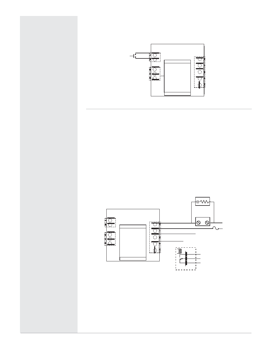
Figure 8a —
External Reset Switch
• Momentary normally open (N.O.), dry contact closure
1
2
3
4
5
6
10
9
8
7
SW-2
SW-1
Momentary N.O. Switch
(customer supplied)
Figure 8b —
Mechanical Relay Output
• Form C contacts
• 8 A, resistive
• 250 VA pilot duty, 120/240V
Å (ac), inductive
• 240V
Å (ac) maximum
• 30V
Î (dc) maximum
• See Quencharc note
• For use with ac or dc
• Minimum load current 100 mA
• Output does not supply power
Internal Circuitry
COM.
N.O.
Mechanical Relay
N.C.
Normally Open
Common
Normally Closed
L1
L2
External
Load
Customer supplied Quencharc
for pilot duty, inductive loads
only. See note.
1
2
3
4
5
6
10
9
8
7
C
N.C.
N.O.