Installing the din rail mount controller, Sub-panel mounting, Din rail mounting – Watlow Series L Temperature Limit User Manual
Page 5: Removing the din rail controller, Removing the controller from the din rail bracket, Spade terminal model, Screw terminal model, Tactile key model
Wa t l ow S e r i e s L
• 3 •
C h a p te r 2 : I n s t a l l a t i o n
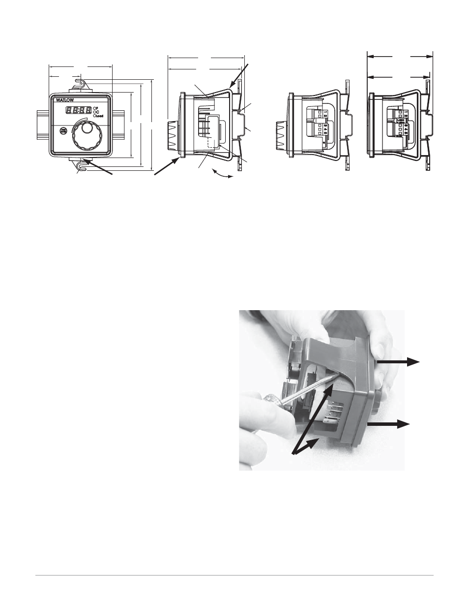
Figure 3a
Sub-Panel Mounting
1. Using the controller as a location template, mark
both mounting holes.
2. Drill and tap two 2.7 mm (0.106 in) diameter
holes in the desired panel location. See Figure
3a above for hole locations.
3. Mount the controller using two M3.5
(#6) screws.
DIN Rail Mounting
1. Place the DIN rail upper mounting clip on the top
edge of the DIN rail. See Figure 3a. DIN rail
spec, DIN 50022, 35 mm x 7.5 mm (1.38 in x 0.30
in).
2. Press down firmly on the top back edge of the DIN
rail bracket and push in on the bottom, front edge
of the bracket. The controller snaps securely onto
the rail. See Figure 3a. If the controller does
not snap on, check to see if the DIN rail is bent.
Minimum clipping distance is 34.8 mm (1.37 in),
the maximum is 35.3 mm (1.39 in).
Removing the DIN Rail Controller
1. Remove power from the system.
2. Remove all the wiring connections from the back
of the controller.
3. While pressing down on the top, back edge of the
DIN rail bracket, pull forward on the bottom, front
edge of the DIN rail bracket. See Figure 3a.
Removing the Controller from the DIN
Rail Bracket
1. Remove power from the system.
2. Remove all the wiring connections from the back
of the controller.
3. Remove the DIN rail bracket from the DIN rail.
4. Insert a flat blade screwdriver between the DIN
rail bracket and the case. Rotate the screwdriver
to release the DIN rail bracket hooks from the
ridges on the case, while firmly pushing the con-
troller out the front of the DIN rail bracket. Al-
ternate back and forth between the top and then
the bottom. Be sure to support the controller as it
comes out of the bracket. See Figure 3b.
Figure 3b
ç
Caution: FM approval requires limit switches to be suit-
ably enclosed to restrict casual user adjustment.
Installing the DIN Rail Mount Controller
Spade Terminal Model
SW-1
SW-2
TC-/S1
TC+/S2
S3
Screw Terminal Model
78.1 mm
(3.08 in)
39.1 mm
(1.54 in)
Panel mounting the bracket requires
two M3.5 (#6) screws, not included
To install, press in here.
To remove, pull out here.
See Mounting/Removing the
DIN Rail Controller procedures below.
80.3 mm
(3.16 in)
101.6 mm
(4.00 in)
112.3 mm
(4.42 in)
94.7 mm
(3.73 in)
90.7 mm
(3.57 in)
Part Number Label
To install or remove,
press down here.
See Installing/ Removing
the DIN Rail Controller
procedures below.
DIN rail, upper
mounting clip
35 mm x 7.5 mm
DIN rail is not included
with the assembly
Terminal Designation Sticker
Agency Label
81.8 mm
(3.22 in)
80.0 mm
(3.07 in)
1.
2.
3.
4.
5.
Tactile Key Model
Press forward
with thumb.
Insert fl at blade screw-
driver here.