Wiring – Watlow Series L Temperature Limit User Manual
Page 8
Wa t l ow S e r i e s L
• 6 • C h a p te r
3 :
Wi r i n g
Ó
Warning:
Use National Electric (NEC) or
other country-specifi c standard
wiring and safety practices
when wiring and connect-
ing this controller to a power
source and to electrical sen-
sors or peripheral devices. Fail-
ure to do so may result in dam-
age to equipment and property,
and/or injury or loss of life.
Note:
Insulated terminals required for
quick connect style terminals.
For quick connect terminals
1, 2, 6, 7, 8, 9, and 10, AMP
P/N 3-520406-2 or equivalent
recommended. Use Amp crimp
tool P/N 58078-3, insert 90391-
3.
For quick connect terminals 3,
4, and 5, AMP P/N 2-520405-2
or equivalent recommended.
Amp crimp tool P/N 58078-3,
insert 58079-3.
ç
Caution:
FM approval requires limit
switches to be suitably en-
closed to restrict casual user
adjustment.
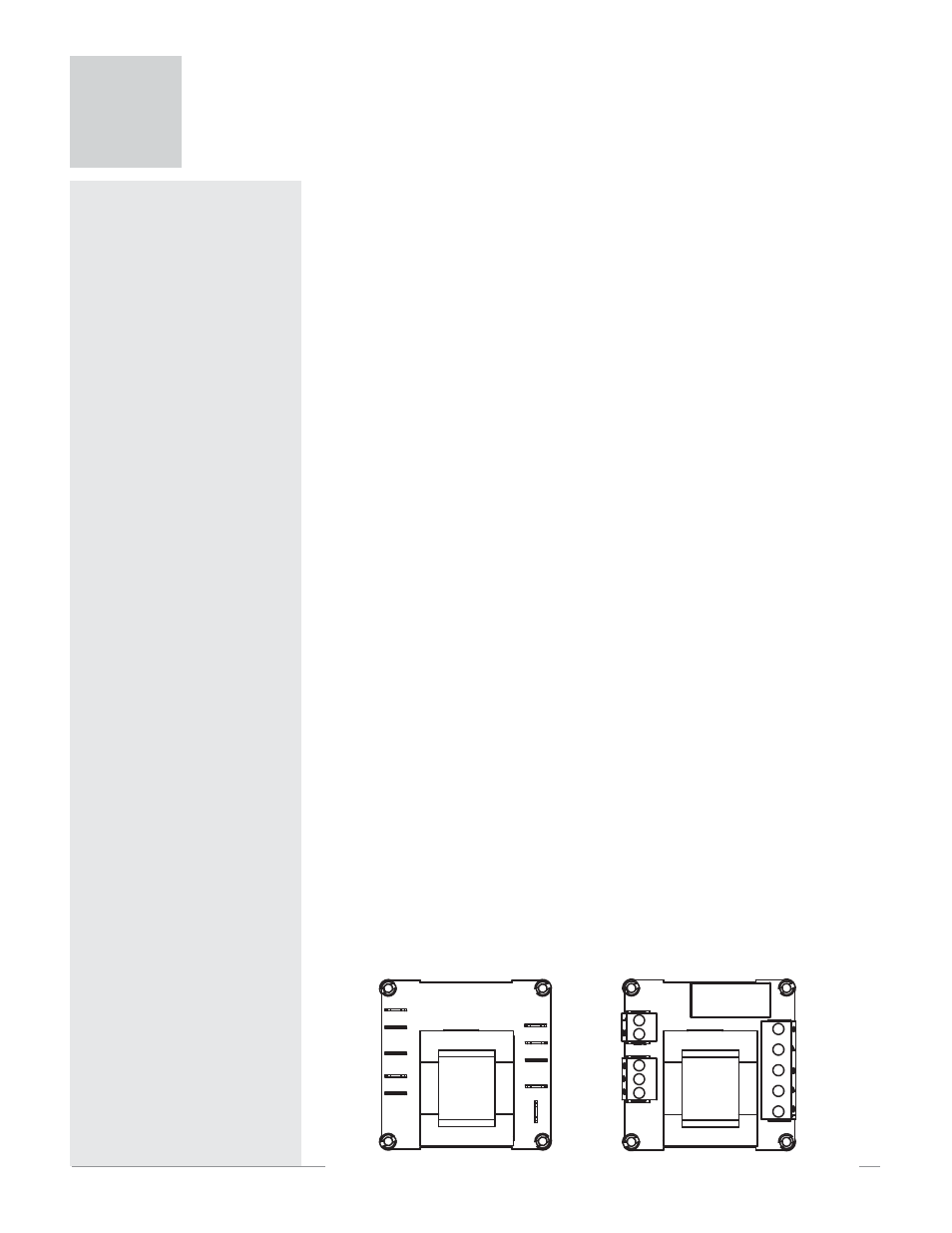
The terminals on the back of the Series L limits are the same for all of the
package styles. They are 6.3 mm (0.25 in) quick connect, push on style ter-
minals or removable screw terminal block. The terminal style is an ordering
option.
Check the part number to determine your hardware configuration. Refer
to the wiring diagrams appropriate for your controller’s configuration.
All outputs are referenced to a de-energized state.
Wiring Guidelines
1. Use the correct thermocouple type per the model number on the case
sticker of the unit. See dimension drawings for sticker locations.
• Use correct thermocouple polarity. Red is usually negative.
• If you must extend thermocouple leads, use thermocouple extension
wire to minimize errors.
• Be sure you have good crimp connections on all wire connections.
• Insulate the thermocouple mounting from the mounting surface to
prevent heat migration input errors.
• Thermocouple leads should be routed separately from any high volt-
age lines.
• Long lead lengths create electrical resistance. When using a two-wire
RTD, there will be an additional 2.6° C (4.7° F) error for every 1Ω of lead
length resistance. That resistance when added to the resistance of the
RTD element, can result in erroneous input to the temperature control-
ler.
2. In electrically-noisy environments (heavy switching contactors, motors,
solenoids, etc.), use shielded thermocouple lead wire with the shield con-
nected at the sensor end only.
3. Use a separate thermocouple to maintain the limit function of this
controller; do not parallel thermocouple input from the primary control-
ler.
4. All wiring and fusing must conform to the National Electric Code (NEC)
NFPA70 and any other locally applicable codes.
5. Fuse the independent load voltage on the L1 (hot) side and connect it to
the common (C) side of the relay.
Note: The model number determines the connection terminal style. See below for terminal
locations.
1
2
3
4
5
6
10
9
8
7
1
2
3
4
5
6
10
9
8
7
Wiring
3