Input signal wiring, Ca control card — ac input contactor, Cd control card — dc input contactor – Watlow QPAC User Manual
Page 14: Input wiring
14
QPAC User's Guide
Chapter 2: Install & Wire
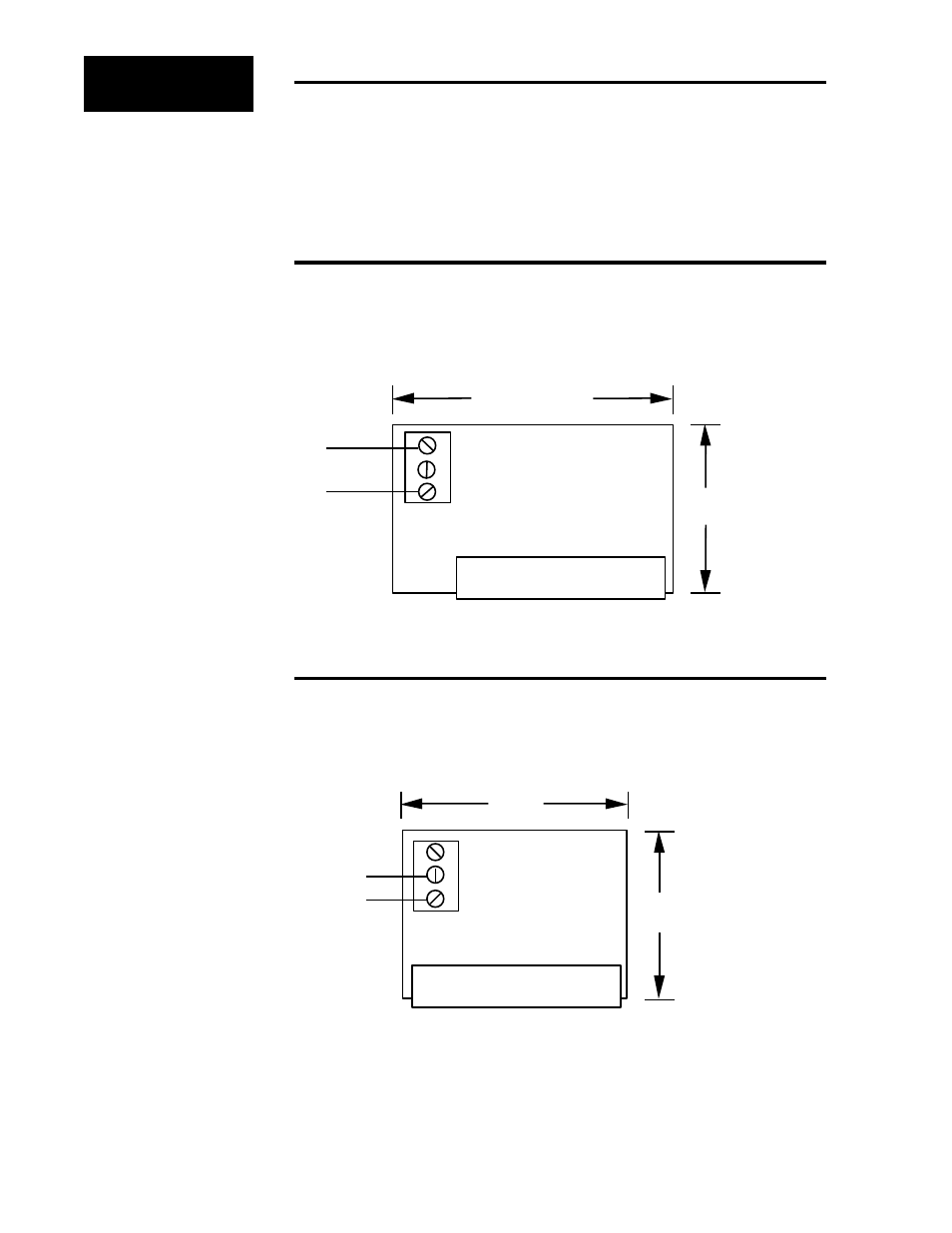
63.5mm (2.50 in)
Motherboard Connector
1
120VÅ (ac)
Input
38.1mm
(1.50 in)
2
3
08-5285
Input Signal Wiring
When wiring the input signal do not run any signal wires alongside or in the
same conduit with the ac power or load wires. Signal input should be pro-
vided by a shielded, two-conductor wire. Shield should be grounded at the
temperature control end only. Wrap the power control end with electrical
tape. The following figures show the wiring configuration for the input signal
to the QPAC Control Cards.
CA Control Card — AC Input Contactor
The 120VÅ (ac) input (24 volts input optional) signal lines for the CA (ac In-
put, Solid-State Contactor) Control Card are connected to pins 1 and 3 of the
input signal connector. A 120VÅ (ac) input signal turns the power control on.
The turn off voltage for the power control is 0VÅ (ac).
Input Wiring
ç
CAUTION:
Built-in noise reduction
circuitry on the CA card
requires an external load
resistor (1000Ω, 25W,
typical) across the input
when operating from a
triac source, to prevent
false triggering. Failure
to apply this resistor
could result in damage
to product and equip-
ment or injury to person-
nel.
CA Card Wiring SS
Contactor, 120V
Å
(ac)
Input.
Motherboard Connector
1
Pin 2 (+)
Pin 3 (-)
51mm
(2.00 in)
38mm
(1.50 in)
2 (+)
3 (-)
08-5286
CD Control Card — DC Input Contactor
For dc input, the input signal is wired into pin 2 (+) and pin 3 (-) of the input
signal connector. An input signal of 3 to 30VÎ (dc) turns the QPAC power
control on. 0 to 1VÎ (dc) turns the power control off.
CD Control Card, Solid-
State Contactor, 3 to
30V
Î
(dc) Input.