Winch frame mounting, Cable installation / tensioner operation, Hydraulic system requirements – Ramsey Winch RPH-30000T-117 User Manual
Page 4
WINCH FRAME MOUNTING
Use (8) 5/8 inch diameter grade 5 or better bolts to attach mounting frame to wrecker.
CABLE INSTALLATION / TENSIONER OPERATION
CAUTION: The cable tensioner is not intended to be energized on a bare drum. Before applying air to the cable tensioner, engage the clutch
and run the winch in the reel in direction winding one full wrap of cable on the drum. This prevents damage to the cable tensioner.
1. Unwind cable by rolling it out along the ground to prevent kinking. Securely wrap end of wire rope, opposite hook, with plastic or similar
tape to prevent fraying.
2. Insert the end of cable, opposite hook end, into the hole in drum barrel. Secure cable to drum barrel, using setscrew furnished with
winch. TIGHTEN SETSCREW SECURELY.
3. Engage the clutch and carefully run the winch in the "reel-in" direction. Keeping tension on end of cable, spool about five wraps of cable
onto the drum and stop. Using a hammer, tap these five wraps tightly over against the cable anchor flange side of the cable drum. Finish
winding all the cable onto the cable drum. As cable winds onto the drum, watch the tensioner. Tensioner must be free to move without
obstruction to function properly. If tensioner touches any surrounding structure, correct the problem.
Adjust the Free-spool Effort of the Cable Tensioner
Disengage the winch clutch and free spool some cable off the drum. Adjust the air pressure to the cable tensioner to achieve the desired free
spool effort that also prevents "bird nesting" of the cable.
CAUTION: DO NOT EXCEED 80 PSI AIR PRESSURE TO THE AIR TENSIONER ACTUATORS.
Once you have adjusted the air pressure to the desired level, only minor adjustment may be required if your pressure regulator setting drifts.
HYDRAULIC SYSTEM REQUIREMENTS
Refer to the performance charts, on page 3, to properly match your hydraulic system to RPH 30000T-117 winch performance. The charts
consist of :
(1) Line pull (lb.) first layer vs. working pressure (PSI) and (2) Line speed, first layer (FPM) vs. gallons per minute (GPM). Performance
based on a 2 speed motor displacement of 9.6/4.8 cubic inches with 15 GPM maximum flow rate. See page 14 for motor port size.
2
B
A
BRAKE
PORT
MOTOR
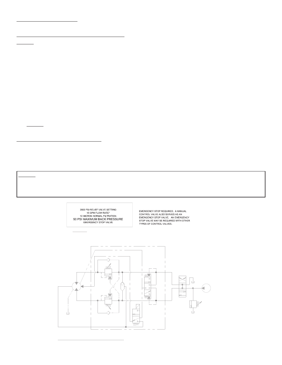
HYDRAULIC SYSTEM SCHEMATIC
SYSTEM
RELIEF
MAX. FLOW &
PRESSURE AT
RATED LOAD:
15 GPM
2800 PSI
PUMP
3 POSITION
4 WAY VALVE
(MOTOR SPOOL)
DUAL - A & B PORT
MOTOR CONTROL VALVE
WITH BRAKE RELEASE SHUTTLE
SYSTEM REQUIREMENTS:
*CAUTION: DO NOT EXCEED 20 GPM, IF EXCEEDED, MOTOR AND WINCH MAY BE DAMAGED
INSTALLER MUST DETERMINE TYPE OF
OPTIONAL
EXTERNAL
CASE DRAIN
LINE
CAUTION: SYSTEM BACK PRESSURE MUST NOT EXCEED 50 PSI OR BRAKE SHAFT SEAL FAILURE CAN OCCUR. IF BACK PRESSURE
EXCEEDS 50 PSI, AND CANNOT BE REDUCED, AN EXTERNAL CASE DRAIN LINE SHOULD BE RUN FROM THE MOTOR CASE DRAIN PORT
(SEE PAGE 15) TO TANK OR A LINE/CONNECTION THAT HAS A PRESSURE BELOW 50 PSI. THE DRAIN LINE MUST BE ROUTED SO THAT
SOMEWHERE ALONG ITS PATH, THE LINE IS HIGHER THAN THE MOTOR SHAFT CENTERLINE.