Ramsey Winch RPH-30000T-117 User Manual
Page 12
9.
NOTE: DETERMINE MOUNTING CONFIGURATION OF WINCH (R.H. or L.H. MOUNTED) BEFORE ATTACHING
UPRIGHT FRAME TO WINCH, TO ASSURE PARTS ARE MOUNTED TO PROPER SIDE, REFER TO WINCH
MOUNTING CONFIGURATIONS, STEP 15 PAGE 13.
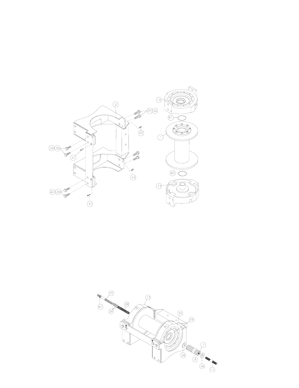
Seat well oiled quad-rings (item #60 & #61) into groove of bushing in each end of drum assembly (item #1), as shown.
Carefully set drum assembly (item #1) down over motor end bearing (item #11). Lift gear housing end bearing (item
#10) and set into place on drum assembly. Attach upright frame (item #2) to end bearings. Install shoulder bolts
(item #40 & #41) and hand tighten. Install (4) capscrews with lockwashers (item #24 & #35) and (4) capscrews with
lockwashers (item #25 & #35), as shown. Tighten (4) inner-most capscrews securely, check rotation of cable drum.
Tighten (4) outer-most capscrews securely, check rotation of cable drum. Torque capscrews, in above inner-most
then outer-most pattern, to 250 ft. lbs. each. Torque (4) shoulder bolts to 30 ft. lbs. each. Make sure cable drum
assembly rotates freely at this point.
10.
Liberally apply grease to splined ends of input shaft (item #13). Place (3) washers (item #39) and spring (item #68)
over longest splined end of shaft. Use grease to hold washer and spring in place on shaft and against snap ring
(item #67). Place spring (item #68) and longest splined end of shaft through motor end bearing (item #11) and drum
until shaft extends through bushing (item #19). Place clutch washer (item #36) over splined end of shaft and against
spring.
Place end of output coupling assembly (item #8), with longest spline inward, through end bearing bushing (item #19)
and mesh shaft coupling spline (item #7) with splined end of input shaft. Place short splined end of shifter shaft
(item #14) through washer (item #36) and into shaft coupling (item #7), meshing splines of shifter shaft with splines
in shaft coupling.
10