Test procedure for motor – Ramsey Winch DC-200 SERIES RAM-LOK User Manual
Page 27
25
TEST PROCEDURE FOR MOTOR
The Ramsey Winch motor is a (4 pole-4 coil)series wound 12 volt or 24 volt DC motor. The 4 pole,
4 coil feature provides high torque at low speeds.
To test the motor to determine if it is functioning properly, fi rst securely fasten the motor to a bench
or work surface so it will not jump or move around during test procedure (the starting torque of mo-
tor is high).
1.
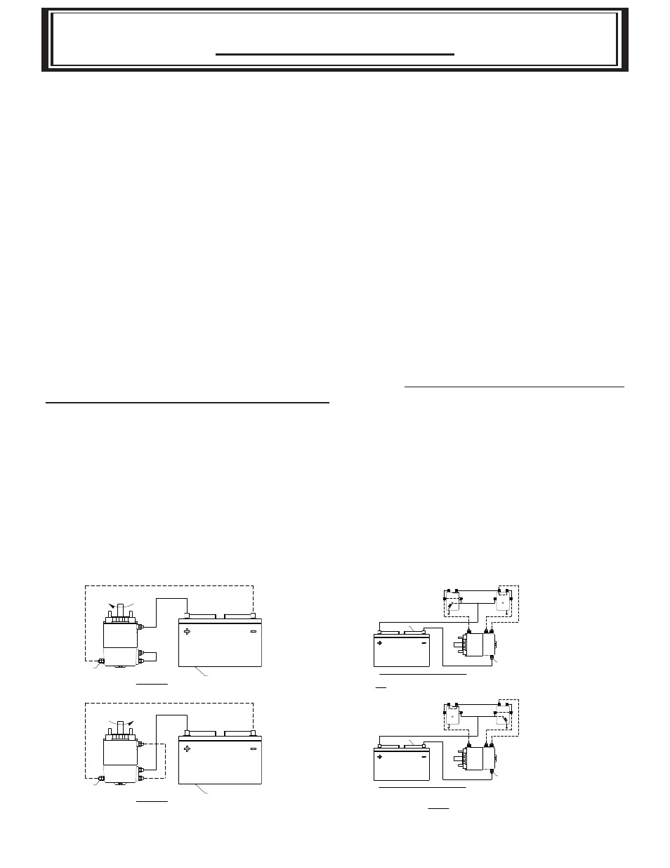
Connect a jumper wire (at least a number 6 wire)from F-1 to “A” motor terminals
(See Figure 1)
2. Attach a wire (at least a number 6 wire) from positive (+) battery terminal to F-2 motor ter-
minal. Ground negative (-) battery terminal to motor isolated ground terminal
(See Figure 1). Motor should now run.
To reverse the direction of rotation:
1. Attach jumper wire from F-2 to “A” motor terminals (See Figure 2).
2. Attach wire from positive {+) battery terminal to F-1 motor terminal. Ground negative (-)
battery terminal to motor housing (See Figure 2).
NOTE: Always attach battery wire solidly to motor terminals. Make and break the connection of the
negative (-) battery terminal at the motor housing. This avoids burning the motor terminals.
CAUTION: Do not run the motor for a long period of time in fashion mentioned above, because the
motor could become damaged.
The motor running idle on the bench will draw 55 amperes and must run free and easy. If the am-
pere draw is more than 60 amps and the motor runs rough or has a strange sound, it should be re-
placed. With the motor attached in place on a winch (less cable on drum) the ampere draw should
be approximately 65 to 70 amps. If after following the procedure outlined, the test on the winch
signifi cantly exceeds 70 amperes refer to your Owners Manual for trouble shooting suggestions on
the mechanical portion of the winch.
See Figure 3 for the solenoids connection to the motor and the battery.
TEST PROCEDURE FOR MOTOR
F2
F1
A
ISOLATED
GROUND
BATTERY
CW
MOTOR-CLOCKWISE ROTATION
MOTOR-COUNTER CLOCKWISE ROTATION
CCW
BATTERY
ISOLATED
GROUND
A
F1
F2
FIGURE-1
FIGURE-2
A
F1
F2
ISOLATED GROUND
TERMINAL
BATTERY
THE DASHED LINES ARE CURRENT'S PATH IN FORWARD ROTATION.
SOLID LINES ARE CURRENT'S PATH AT ALL TIMES.
NOTE: DIRECTION OF MOTOR ROTATION DEPENDS ON WHICH SMALL
TERMINAL OF EITHER SOLENOID IS CONNECTED TO BATTERY'S
POSITVE TERMINAL.
BATTERY
ISOLATED GROUND
TERMINAL
F2
F1
A
THE DASHED LINES ARE CURRENT'S PATH IN REVERSE
ROTATION. SOLID LINES ARE CURRENT'S PATH AT ALL TIMES.
SOLENOIDS TO MOTOR CONNECTIONS
SOLENOIDS TO MOTOR CONNECTIONS
FIGURE-3