Operation, B-24 – Lincoln Electric IM10038 POWER WAVE C300CE User Manual
Page 44
B-24
OPERATION
B-24
POWER WAVE® C300 CE
Shielding
Gas
Id le
Preflo w
Stri ke
Weld
Burnb ack
Postflow
Idl e
WFS
On
Off
Ru n-in
Off
We ld
Off
We ld
Arc
Established
T
rigger
Pulled
T
rigger
Released
4 St ep Trigge r
St art = OFF
C rater = OFF
B urnback = OF F
1. 5 s ec max.
Start
Cra te r
Po wer
So urce
Output
Crater
T
rigger
Pulled
T
rigger
Released
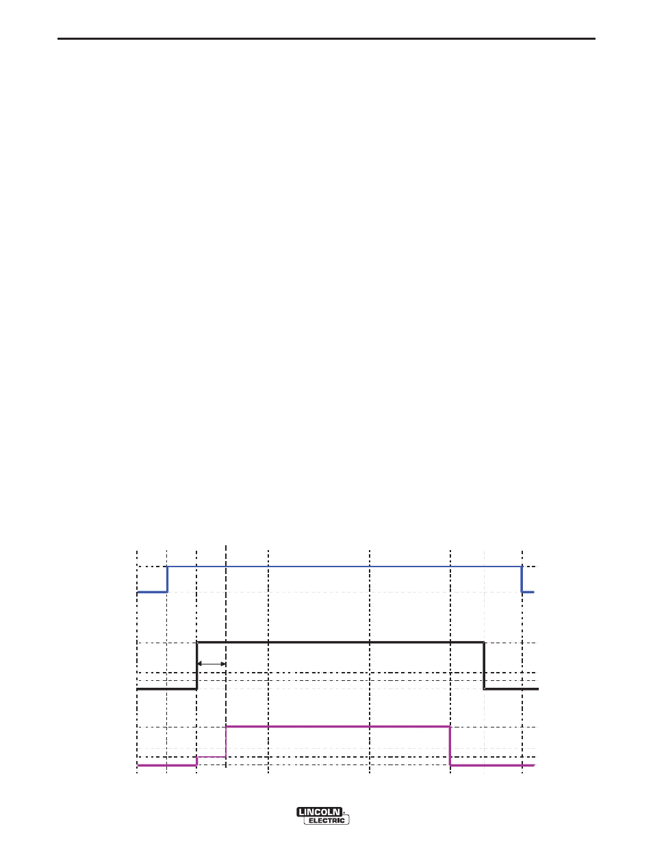
FIGURE B.14
EXAMPLE 4 – 4 STEP TRIGGER: Trigger Interlock
The 4 step trigger can be configured as a trigger inter-
lock. Trigger interlock adds to the welderʼs comfort
when making long welds by allowing the trigger to be
released after an initial trigger pull. Welding stops
when the trigger is pulled a second time and then
released, or if the arc is interrupted. (See Figure B.14)
For this sequence,
PREFLOW:
Shielding gas begins to flow immediately when the
gun trigger is pulled.
RUN-IN:
After preflow time expires, the power source regulates
to the welding output and wire is advanced towards
the work piece at the Run-In WFS. If an arc is not
established within 1.5 seconds, the wire feed speed
will jump to the welding wire feed speed.
WELD:
The power source output and the wire feed speed
continue at the weld settings. Welding continues when
the trigger is pulled a second time.
POSTFLOW:
As soon as the trigger is released for the second time,
the power source output and the wire feed speed are
turned OFF. Shielding gas flows until the post flow
timer expires.