Operation, Case front controls – Lincoln Electric IM10038 POWER WAVE C300CE User Manual
Page 24
B-4
OPERATION
B-4
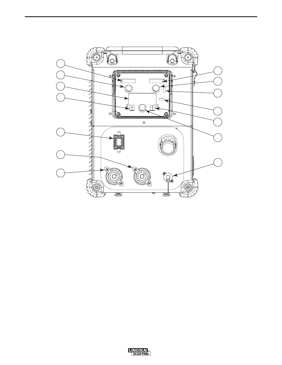
CASE FRONT CONTROLS
All operator controls and adjustments are located on
the case front of the Power Wave. (See Figure B.1)
1. LEFT DISPLAY- Shows wire feed speed or amper-
age,
2. LEFT KNOB- Adjusts value in left display.
3. MAIN DISPLAY- Shows detailed welding and diag-
nostic information.
4. LEFT BUTTON- Changes the Main display to
show the Weld Mode or UltimArc™ Control or
Memories.
5. ON/OFF SWITCH- Controls power to the Power
Wave C300CE.
6. + OUTPUT STUD- Connection for electrode posi-
tive.
7. - OUTPUT STUD- Connection for electrode nega-
tive.
8. RIGHT DISPLAY- Shows voltage or trim.
9. RIGHT KNOB- Adjusts value in right display.
10. THERMAL LIGHT- Indicates when machine has
thermal fault.
11. SET-UP- Lights when machine is in set-up mode,
12. RIGHT BUTTON- Changes the Main display to
arc start, arc end and trigger options.
13. MAIN KNOB- Changes the values on the Main
display.
14. 12 PIN CONNECTOR- Connection for push pull
guns, remotes.
POWER WAVE® C300 CE
1
2
3
4
5
6
7
8
9
10
11
12
13
14
FIGURE B.1
- Invertec V310-T DC (2 pages)
- VANTAGE 500 (CE) 11575 (50 pages)
- INVERTEC V350-PRO SVM152-A (155 pages)
- IMVERTEC V160-T (36 pages)
- IDEALARC CV-300 (112 pages)
- INVERTEC POWER WAVE 450 SVM112-B (293 pages)
- AUTO-DARKENING HELMET IM10001 (12 pages)
- IM10111 IDEALARC R3R-500-I (28 pages)
- IM10110 IDEALARC R3R-400 (25 pages)
- IM10051 INVERTEC V311-T AC_DC (38 pages)
- IM10059 SQUARE WAVE TIG 175 (30 pages)
- IM10096 POWER MIG 256 (37 pages)
- IM10096 POWER MIG 256 (38 pages)
- IM10105 POWER MIG 350MP (47 pages)
- IM10115 FLEXTEC 650 (42 pages)
- IM10132 FLEXTEC 650 (56 pages)
- IM10132 FLEXTEC 650 (36 pages)
- IM10018 IDEALARC DC-600 VRD (55 pages)
- IM10107 IDEALARC DC-400 (40 pages)
- IM10062 FLEXTEC 450 (72 pages)
- IM10091 FLEXTEC 450 CE (40 pages)
- IM10094 RED-D-ARC FX450 (31 pages)
- IM10157 12_24V 10A Auto HF Household Charger (16 pages)
- IM10139 JUMP STARTER (12 pages)
- IM10149 POWER WAVE ADVANCED MODULE (46 pages)
- IM10102 AIR VANTAGE 650 (60 pages)
- IM10103 AIR VANTAGE 700 (AU) (57 pages)
- IM10065 AIR VANTAGE 500 CUMMINS (54 pages)
- IM10066 AIR VANTAGE 500 (AU) (56 pages)
- IM10041 VANTAGE 500 CUMMINS (56 pages)
- IM10128 AIR VANTAGE 500 KUBOTA (AU) (56 pages)
- IM10090 ARC TRACKER (48 pages)
- IM10147 AUTO-DARKENING HELMET (12 pages)
- IM10087 AutoDrive 19 CONTROLLER (28 pages)
- IM10125 AutoDrive 19 TANDEM (34 pages)
- IM10069 AutoDrive 4R100 (32 pages)
- IM10145 AUTOPRO 20 (24 pages)
- IM10025 BIG RED 500 (40 pages)
- IM10019 BIG RED 600 (41 pages)
- IM10005 BULLDOG 140 (46 pages)
- IM10074 BULLDOG 5500 (56 pages)
- IM10067 CENTURY AC120 (20 pages)
- IM10109 CIRCULATOR (33 pages)
- IM10109 CIRCULATOR (36 pages)
- IM10153 CLASSIC 300 HE (60 pages)