6 power switch connector – IEI Integration IDDUPS-636260А User Manual
Page 30
IDDUPS Series DC/DC Converter Module
Page 30
Output power cable for SATA
(P/N: CB-3PSATA-RS)
Output power cable for IDE or any
standard 4-pin I/O devices
(P/N: CB-3PIDE-RS)
Table 4-11: CN3 & CN4 Connector Cables
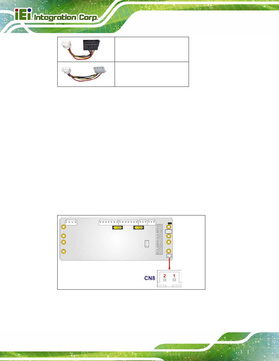
4.2.6 Power Switch Connector
CN Label:
CN8
CN Type:
2-pin wafer connector (1x2)
CN Location:
See
214H214H214H217H
Figure 4-9
CN Pinouts:
See
215H215H215H218H
Table 4-12
This connector connects to a power switch to activate or inactivate the power module. To
prevent the connected Li-Polymer smart batteries from losing power, please inactivate the
power module while not in use. To keep the power module always being able to be
activated, please short pin 1 and pin 2 of the power switch connector (CN8).
Figure 4-9: Power Switch Connector Locations