1 iddups-6364120/636260 system block diagram – IEI Integration IDDUPS-636260А User Manual
Page 13
IDDUPS Series DC/DC Converter Module
Page 13
2.1 IDDUPS-6364120/636260 System Block Diagram
191H191H191H194H
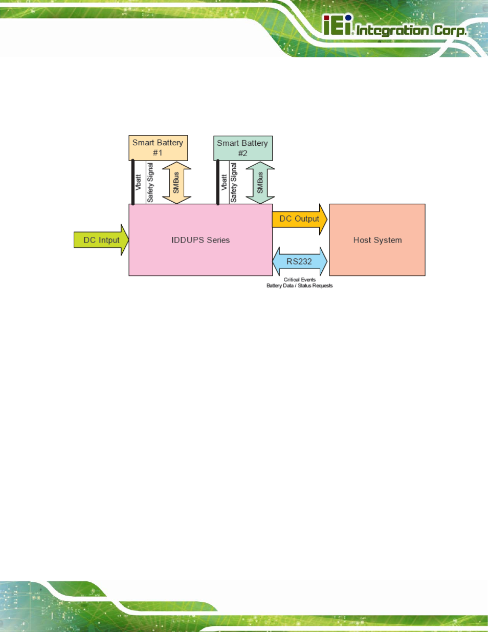
Figure 2-1
shows the system block diagram of the IDDUPS-6364120/636260. The
detailed descriptions of the system operation are described in the following sections.
Figure 2-1: IDDUPS-6364120/636260 System Block Diagram
The IDDUPS series is a charging circuit that provides the Smart Battery with charging
current and charging voltage from DC input to match the requirements from Smart Battery.
The IDDUPS series also provides DC output power to the Host System with following
features:
Provide stable and uninterruptible power to equipment during a power outage,
line sags and spikes
Absorb power surges and transients
Smooth out noisy power sources
The IDDUPS series receives critical events from the Smart Battery when it detects a
problem. The Smart Battery communicates with IDDUPS series via two separate
communication interfaces:
The SMBus CLOCK and DATA lines (primary communication channel)
The secondary signaling mechanism or Safety Signal (secondary
communication channel)