4 jumper settings, 1 at/atx power mode select jumper, Umper – IEI Integration PICOe-HM650 User Manual
Page 68: Ettings, Table 4-1: jumpers, 1 for more details
PICOe-HM650 Half-size PCIe CPU Card
Page 54
4.4 Jumper Settings
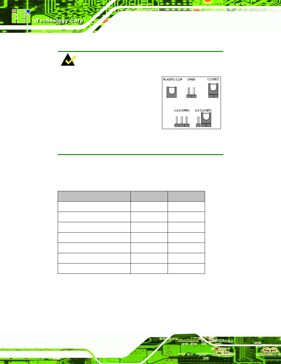
NOTE:
A jumper is a metal bridge used to close
an electrical circuit. It consists of two or
three metal pins and a small metal clip
(often protected by a plastic cover) that
slides over the pins to connect them. To
CLOSE/SHORT a jumper means
connecting the pins of the jumper with
the plastic clip and to OPEN a jumper means removing the plastic clip
from a jumper.
Before the PICOe-HM650 is installed in the system, the jumpers must be set in
accordance with the desired configuration. The jumpers on the PICOe-HM650 are listed in
7
Table 4-1.
Description
Label
Type
AT/ATX power mode select
J_ATXCTL1
3-pin header
Clear CMOS
J_CMOS1
3-pin header
LVDS voltage select
J_VLVDS1
3-pin header
LVDS panel resolution select
J_PID1
8-pin header
PCIe status select
J_PCIE1
2-pin header
TPM setting
ME_RTC1
3-pin header
Flash descriptor security override
J_FLASH1
3-pin header
Table 4-1: Jumpers
4.4.1 AT/ATX Power Mode Select Jumper
Jumper Label:
J_ATXCTL1
Jumper Type:
3-pin header