6 external peripheral interface connection, 1 lan connection, Xternal – IEI Integration PCIE-Q670 v1.03 User Manual
Page 75: Eripheral, Nterface, Onnection, Figure 4-15: pcie mini card installation
PCIE-Q670 PICMG 1.3 CPU Card
Page 60
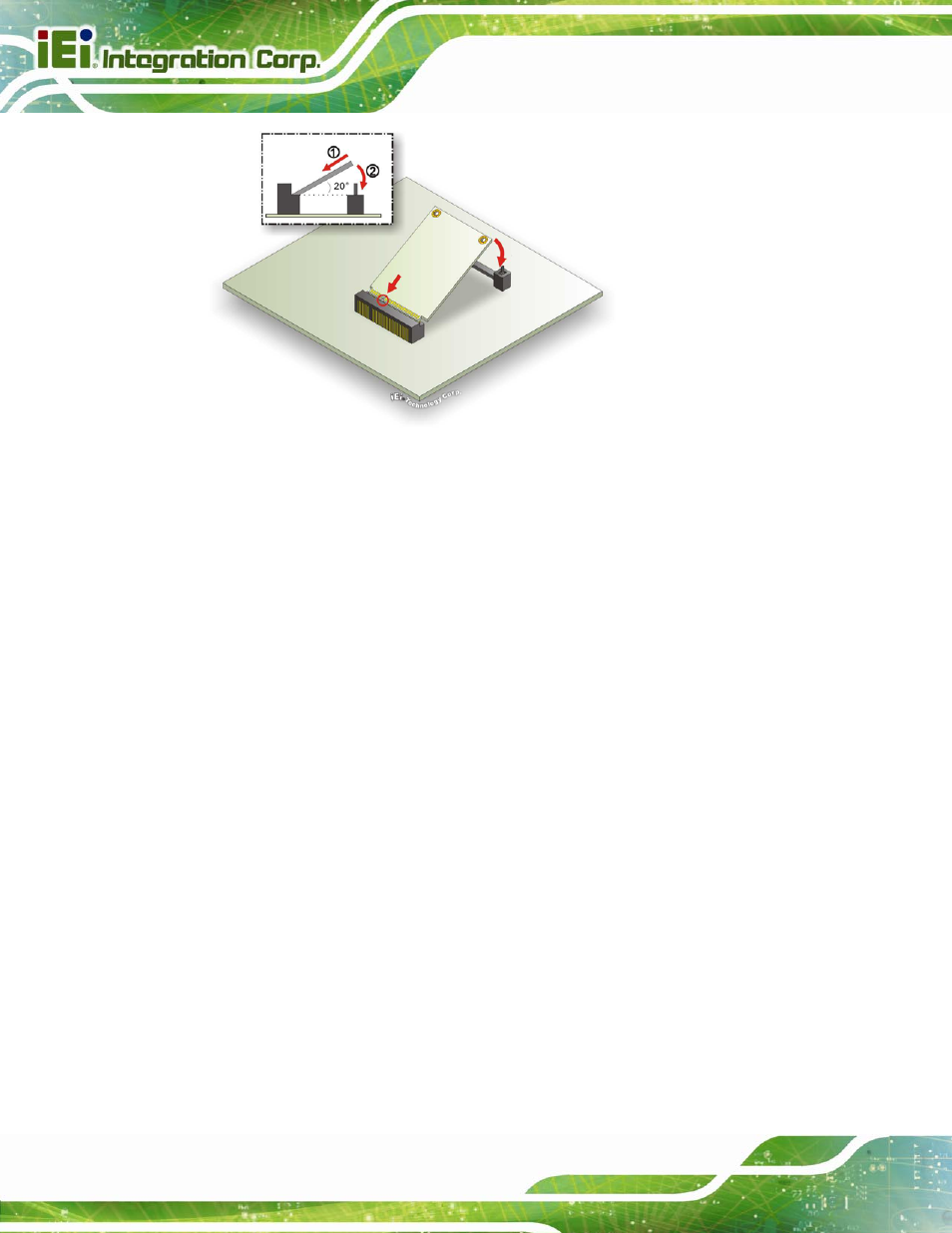
Figure 4-15: PCIe Mini Card Installation
Step 1:
Insert into the socket at and angle. Line up the notch on the card with the
notch on the connector. Slide the PCIe Mini card into the socket at an angle of
about 20º.
Step 2:
Push down until the card clips into place. Push the other end of the card
down until it clips into place on the plastic connector.
4.6 External Peripheral Interface Connection
This section describes connecting devices to the external connectors on the PCIE-Q670
Series.
4.6.1 LAN Connection
There are two external RJ-45 LAN connectors. The RJ-45 connectors enable connection
to an external network. To connect a LAN cable with an RJ-45 connector, please follow
the instructions below.
Step 1:
Locate the RJ-45 connectors. The locations of the RJ-45 connectors are
shown in Chapter 3.
Step 2:
Align the connectors. Align the RJ-45 connector on the LAN cable with one of
the RJ-45 connectors on the PCIE-Q670 Series. See Figure 4-16.