3 jumper settings, 1 at/atx power select jumper, Umper – IEI Integration PCIE-Q670 v1.03 User Manual
Page 66: Ettings, Table 4-1: jumpers
PCIE-Q670 PICMG 1.3 CPU Card
Page 51
Step 4:
Removing a DIMM. To remove a DIMM, push both handles outward. The
memory module is ejected by a mechanism in the socket.
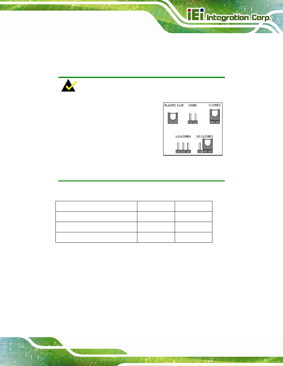
4.3 Jumper Settings
NOTE:
A jumper is a metal bridge used to close
an electrical circuit. It consists of two or
three metal pins and a small metal clip
(often protected by a plastic cover) that
slides over the pins to connect them. To
CLOSE/SHORT a jumper means
connecting the pins of the jumper with
the plastic clip and to OPEN a jumper means removing the plastic clip
from a jumper.
The hardware jumpers must be set before installation. Jumpers are shown in Table 4-1.
Description
Label
Type
AT/ATX power select
JATX_AT1
2-pin header
Clear CMOS jumper
J_CMOS1
3-pin header
Wake-on LAN
WOL_SEL1
3-pin header
Table 4-1: Jumpers
4.3.1 AT/ATX Power Select Jumper
Jumper Label:
JATX_AT1
Jumper Type:
2-pin header
Jumper Settings:
Jumper Location:
The AT/ATX Power Select jumper specifies the systems power mode as AT or ATX.