Warning – WEATHER GUARD 239 User Manual
Page 2
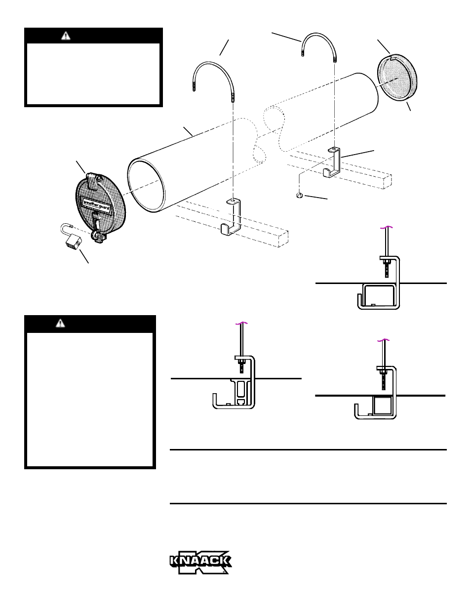
7. Place the Conduit Carrier in position
on your ladder rack. Install the "U"
Clamps and Clamp Brackets (
see Fig-
ure 1.). (See Figures 2a, 2b and 2c for
installation of "U" Clamps and Clamp
Brackets for your crossmember). Be-
fore tightening the nuts, make sure the
conduit carrier is correctly positioned
and the rear door latch is pointing
down as shown in the illustration.
WARNING
Rear end cap door must be pad-
locked during transit to prevent
accidental spillage of contents,
which could cause serious per-
sonal injury or property damage.
If you have any questions, please give us a call. Call Toll Free 1-800-456-7865
Weather Guard® products are protected by one or more of the following patents or trademarks:
U.S. - 842268, 1661625, 1663369; Canada - 282725; U.K. - 1400720; other patents pending.
KNAACK MANUFACTURING COMPANY
420 E. TERRA COTTA AVENUE
CRYSTAL LAKE, ILLINOIS, 60014 - 815-459-6020
© 1993 Knaack Manufacturing Company
- NOTICE -
Any modification or unintended use of this product shall immediately void
all manufacturers warranties. Manufacturer disclaims all liability for injuries
to persons or property resulting from any modification to, or unintended
use of this product.
Rear End Cap
p/n 7073
#12-24 Nylon Lock Nut
(black dichromate)
(4 places)
Clamp Bracket
p/n 20-2390
Front Cap
p/n 21-1015
Triangular
Tab
U-Clamps
p/n 21-1017
(2 places)
PVC Pipe
Padlock
(customer supplied)
Figure 1. Assembly and Installation
on a square shaped crossmember
Figure 2a. Installation on a 211
aluminum crossmember
WARNING
Allow at least 15 minutes for
cement cure time before han-
dling, and we strongly sug-
gest a 24 hour full-cure time
before loading any materials.
If assembled Conduit Carrier
is used before the 24 hour
cure time, the material in the
conduit carrier could push
the end caps out and spillage
of material could occur
causing serious injury to
persons and property.
Figure 2b. Installation on a channel
shaped crossmember
Figure 2c. Installation on a square
shaped crossmember