Mounting anti-rotation, See anti-roatation examples on pages 8-14 – Warner Electric TG-2000 MagStop Clutch_Brake User Manual
Page 6
6
Warner Electric • 800-825-9050
P-1177 • 819-0457
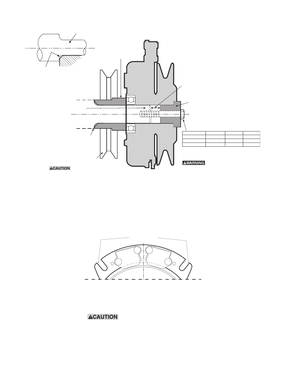
If the field is bolted rigidly
or if its axial movement is restricted, the
bearing in the field assembly will be
improperly loaded and may fail. Use only
factory installed anti-rotation device.
Figure 3
Typical Engine Installation with Ground Drive Pulley
Figure 4
Shaft
Shoulder
Ground
Drive
Pulley
Shaft end and
D-drive
spacer must
not touch
D-drive Spacer
Engine Shaft
Failure to torque bolt
to requirements will
degrade clamping and
can allow the clutch to
separate from the
shaft, causing risk of
personal injury.
Thread size
Torque ft.lb. Torque N-m
3/8-24" UNF
40-45 ft.lb. 54-61 N-m
7/16-20" UNF
50-55 ft.lb. 67-75 N-m
M 10 X 1.50
40-45 ft.lb. 54-61 N-m
Ground drive pulley or spacer
must be chamfered to clear this
radius on the engine shaft
shoulder.
Shaft
Ground Drive Spacer
(or spacer if no ground
round
drive used)
Always bottom the clutch against a
flat surface; never against radius.
Note:
Must have faces parallel to each other
(within .003") and be perpendicular
to the bore.
Note: All values are for dry (unlubricated) plated bolts,
please consult fastener manufacturer if any type of locking
element (thread lock compound, patch etc.) is to be used.
Grade Class
Grade 8
Grade 5 or 8
Grade 10.9
Anti-rotation Slots
Mounting
Anti-Rotation
See Anti-Roatation Examples on pages 8-14