Warner Electric MCS2000-DRV2 User Manual
Page 7
1.
Connect the brown wire [Channel 1 Out (V)]
from the connector cable on the
MCS2000-CT controller to terminal number 1
In A 0 – 10 V on the MCS2000-DRV2. Insure
that the terminal on the MCS2000-DRV2 is
tightened securely.
2.
Connect the green wire [Channel 1 Out (0V)]
from the connector cable on the
MCS2000-CT controller to terminal number 2,
0 V on the MCS2000-DRV2. Insure that the
terminal on the MCS2000-DRV2 is tightened
securely.
If a dual brake system is to be used, then proceed to
step 3.
If only a single brake is to be used on the
MCS2000-DRV2, then skip to either the 24 volt brake
wiring section, page 8 or the 48 volt brake wiring
section, page 10.
3.
Connect the red wire [Channel 2 Out (V)] from
the connector cable on the MCS2000-CT
controller to terminal number 3 In V 0-10 V on
the MCS2000-DRV2. Insure that the terminal
on the MCS2000-DRV2 is tightened securely.
4.
Connect the black wire [Channel 2 Out (0V)]
from the connector cable on the
MCS2000-CT Connector controller to
terminal number 4 on the MCS2000-DRV2.
Insure that the terminal on the
MCS2000-DRV2 is tightened securely.
5.
This completes the wiring between the
MCS2000-ECA and the MCS2000-DRV2.
Double check all wiring before proceeding to
the next section.
6.
Proceed to either the 24 volt brake wiring
section, page 8 or the 48 volt brake wiring
section, page 10 of the manual.
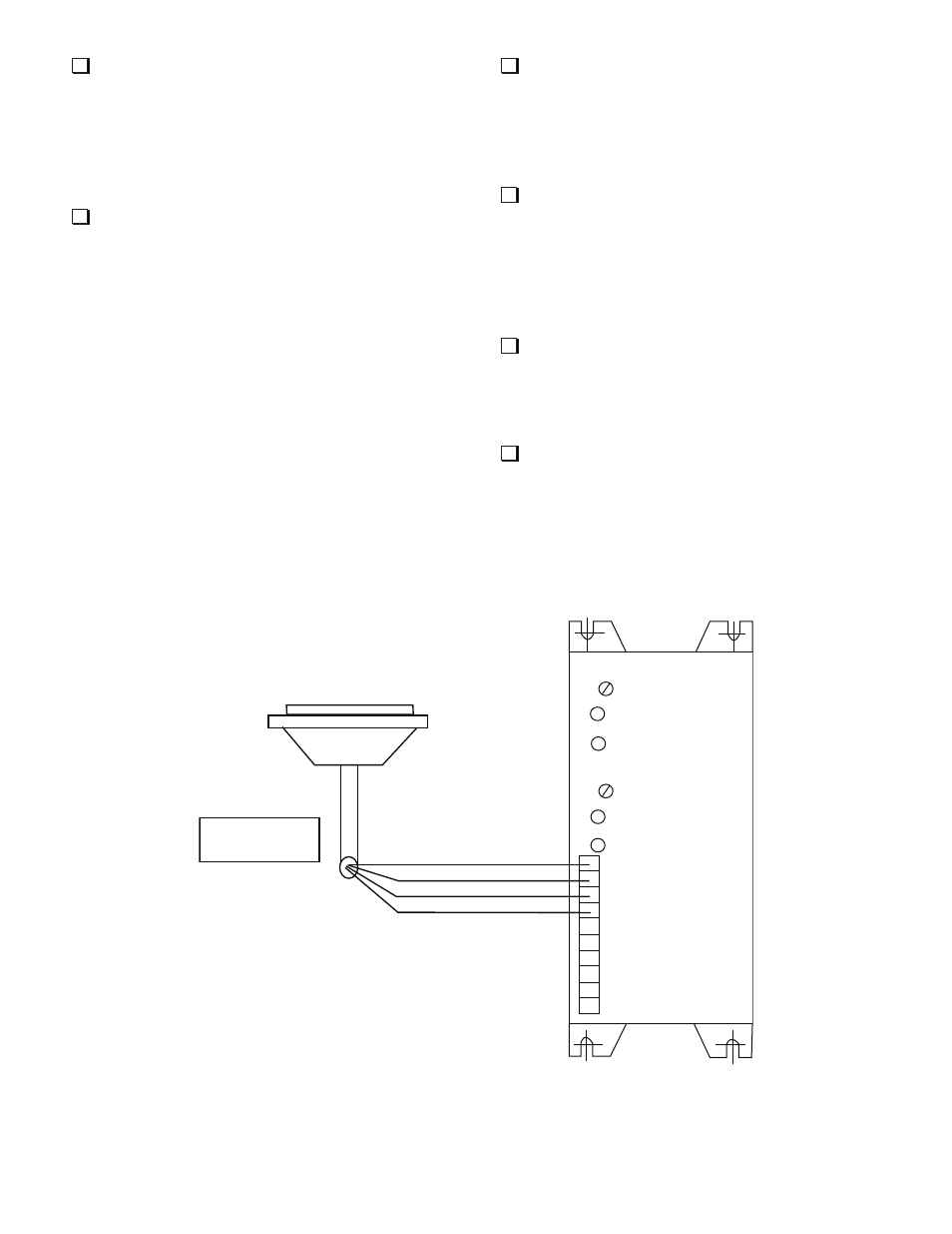
Note: Wiring is shown for both channels. If only
one channel is required, then follow wiring
using only the brown and green wires as shown.
Warner Electric • 800-825-9050
P-2010-6 • 819-0524
MCS2000-CT
Cable Assembly
MSC2000-DRV2
“A” Antiresidual
Channel A
“B” Antiresidual
Channel B
1. In A 0-10V
2. 0V
3. In B 0-10V
4. 0V
5. Brk A+
6. Brk A-
7. Brk B+
8. Brk B-
9. -DC Power
10. + 24 - 48 VDC
(Brown)
(Green)
(Red)
(Black)
MCS2000-CT Cable and Connector
MCS2000-DRV2 Driver
Figure 3
MCS2000-CTDA or MSC2000-CTLC to MCS2000-DRV2
7