Installation, Driver outline and mounting dimensions, Figure 1 mounting dimensions 4 – Warner Electric MCS2000-DRV2 User Manual
Page 4
Installation
Mounting
Select a location that will allow for sufficient air
movement around the control.
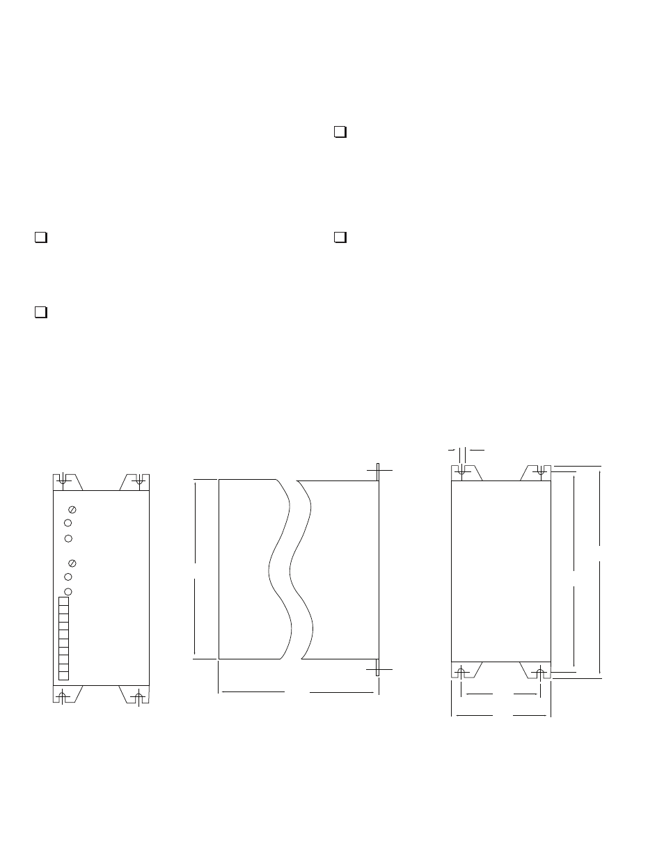
Overall Dimensions: 6.85 x 2.95 x 7.28 inches
(174 x 75 x 185 mm)
Note: Unit must be mounted vertically to have
best possible cooling effect.
1. Using the dimensional data from Figure 1, drill
and tap 4 mounting holes for either 4.5 mm
screws or #10 screws on the panel or
mounting surface the drive will be mounted to.
2. Using either 4.5 mm or #10 screws, mount the
unit to the panel or mounting surface. Tighten
screws sufficiently so that unit will not come
loose during normal machine operation or
vibration.
Note: 0 Volt terminals in control are tied to control
housing. A good ground is required between the
control and the panel or mounting surface.
3. After unit is mounted and secured, make sure
that spacing is sufficient around the housing
and that at least a clearance of at least 2.00
inches (50.8 mm) for the front panel wiring
plug to facilitate wiring unit and plugging
connector to control.
4. Double check all mounting before proceeding
to the wiring section.
Warner Electric • 800-825-9050
P-2010-6 • 819-0524
5.83
(148)
7.28
(185)
.19
(4.8)
6.46
(164)
2.36
(60)
2.95
(75)
6.86
(174)
MSC2000-DRV2
“A” Antiresidual
Channel A
“B” Antiresidual
Channel B
1. In A 0-10V
2. 0V
3. In B 0-10V
4. 0V
5. Brk A+
6. Brk A-
7. Brk B+
8. Brk B-
9. -DC Power
10. + 24 - 48 VDC
Driver Outline and Mounting Dimensions
Figure 1
Mounting Dimensions
4