Warner Electric Gen 2 Clutch_Electrically Released Brake UniModule UM-50FBC, UM-100FBC, UM-180FBC User Manual
Page 4
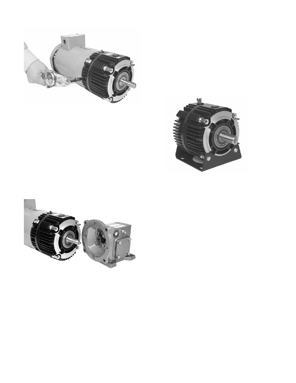
Figure 3b
Mounting to a Reducer
1. Warner Electric UniModules are furnished
with a hardened key pre-mounted on the
output shaft.
2. Align the output shaft and key of the
module with the corresponding bore and
keyway of the reducer. Slide the assembly
together as shown in Figure 4.
Figure 4
3. Bolt the module to the reducer flange.
The four (4) bolts that are required
(3/8-16UNC2A) are typically provided with
the reducer. Tighten to 18-22 foot pounds
of torque.
Installing the Base Mount
Model 2030FBC UniModule is designed to be
base mounted as shown in Figure 5.
Optional Base Mount Kit,
Warner Electric part numbers:
UM-50/100...........................5370-101-004
UM-180................................5370-101-002
Figure 5
1. The pilot diameters on each end of the
UniModule will mate with the pilot
diameters on the base.
2. Secure the base to the UniModule with the
four (4) bolts provided. Tighten to 18 to 22
foot pounds.
Installing the Motor Mount Bracket
A Motor Mount Bracket can be installed on
the output end of a 1020FBC UniModule to
provide a foot mounting for the complete
assembly of a UniModule and C-face motor.
Optional Motor Mount Kit,
Warner Electric part numbers:
UM-50/100............................5370-101-078
UM-180.................................5370-101-079
Warner Electric • 800-825-9050
P-273-9 • 819-0530
4