Tracer Stick AM05016 User Manual
Page 2
Disconnect the Tracer-Stick capsule and hose assembly. Discard the Tracer-Stick and retain the control valves for future use.
As an alternative, you can leave the Tracer-Stick hose assembly in place and substitute male-to-male union or hose extension coupler for the
empty Tracer-Stick. This will allow the Tracer-Stick hose assembly to be left in place for future applications.
Run the A/C system for 5-10 minutes to allow the Fluoro-Lite dye to circulate. Inspect the system with a Tracerline
®
ultraviolet or blue light
lamp. Leaks will glow a bright yellow-green (or green in the case of R-134a/PAG systems). Large leaks will be seen immediately. To discover
smaller leaks, schedule a return visit 24-48 hours later, after the customer has operated the A/C system as much as possible.
WARNING: Ultraviolet light is hazardous if eyes and skin are exposed over time. Ultraviolet light exposure should be minimized by wearing
UV-blocking eyewear and always directing the light source away from one's body and protecting bare skin.
After the repair is completed, it is important to clean off all fluorescent dye residue, otherwise the remaining dye could be
mistaken for a leak indication. To clean, use Tracer Products' water-based GLO-AWAY™ dye cleaner or a general-purpose shop cleaner.
Follow the directions for the cleaner used.
After cleaning, check all areas again with the UV lamp to make sure that no dye residue remains. Run the system a second time and
reinspect with the UV lamp. If there is no glow, all the leaks have been found and repaired.
7
8
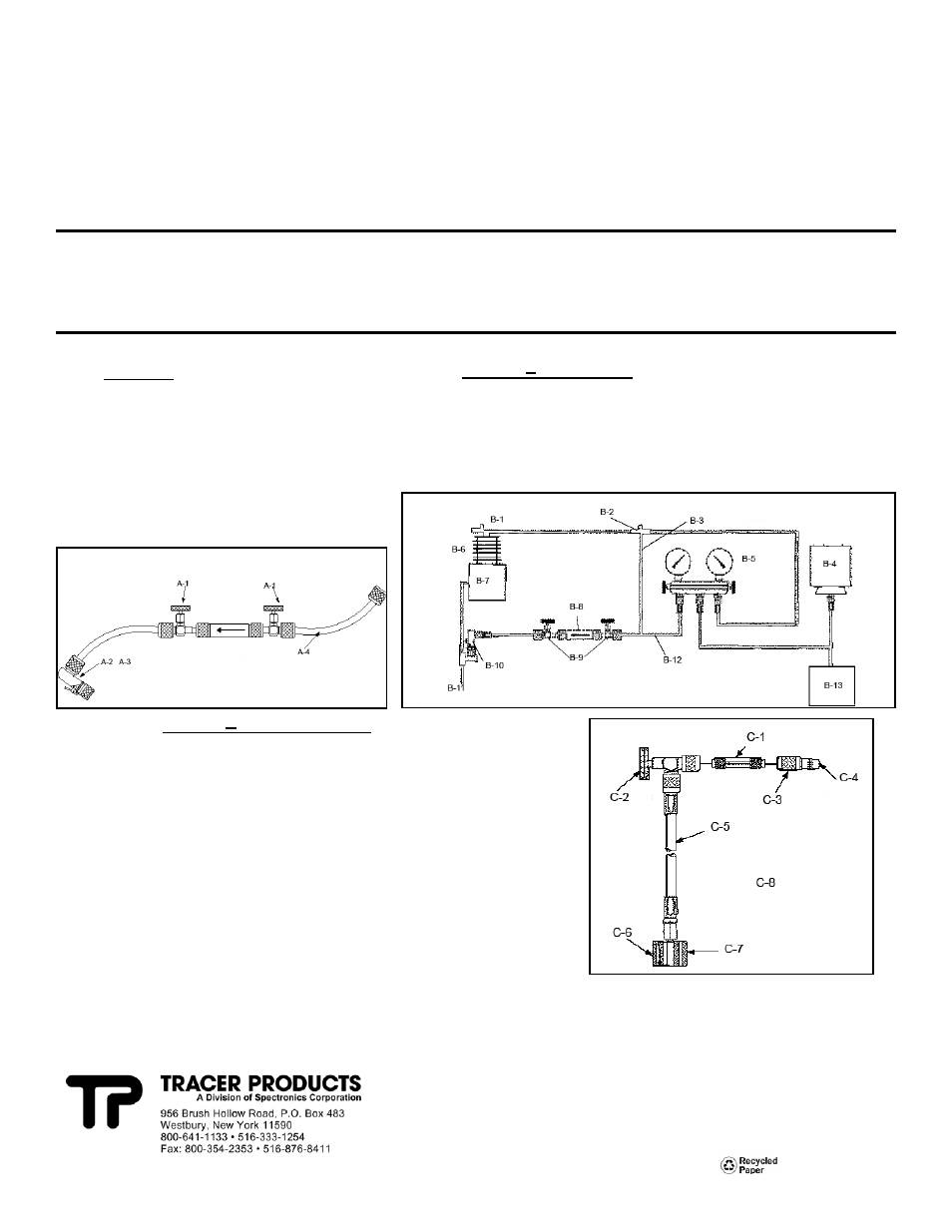
Diagram A
A-1 Control valve
A-2 TP-3852 quick coupler is recommended (for
use with ¼" flare Schrader fittings only)
A-3 Note: for TP-3860 and TP-3870 Tracer-Sticks,
standard R-134a couplers are sufficient
A-4 Whip hoses are recommended
TP-9941 for ¼" flare fittings
TP-9942 for ½" Acme fittings
A
Diagram B Typical Hookup
B-1 Discharge side
B-8 Tracer-Stick capsule
B-2 High-side service port
B-9 Control valves
B-3 See Step 3 (Alternative)
B-10 Quick coupler
B-4 Refrigerant
B-11 Low-side service port
B-5 System analyzer
B-12 Whip hose
B-6 Suction (low side)
B-13 Recovery unit
B-7 Compressor
B
Diagram C
Universal Connect Set
C-1 Tracer-Stick capsule (not supplied with set)
C-2 Control valve
C-3 Service valve fitting
C-4 Connects to quick coupler on manifold or recovery unit
C-5 Hose, 18 inches (46 cm)
C-6 Connects to service port
C-7 Quick coupler
C-8 FOR LOW-SIDE CHARGING
Use TP-3887 for TP-3860 and TP-3870 Tracer-Stick capsules
Use TP-3837 for TP-3865, TP-3866, TP-3867, TP-3875, TP-3876 and
TP-3877 Tracer-Stick capsules
FOR HIGH-SIDE CHARGING
Use TP-9887 for TP-3860 and TP-3870 Tracer-Stick capsules
Use TP-9837 for TP-3865, TP-3866, TP-3867, TP-3875, TP-3876
and TP-3877 Tracer-Stick capsules
C
6/05 AM05016
PRINTED IN U.S.A.
www.tracerline.com