Teledyne LeCroy Power Analyzer Package User Manual
Page 7
Operator's Manual
The Power Analysis dialog is also where you control the display of Statistics or Histicons within the Power
Analysis Measurements table, and Clear Sweeps to reset the measurement counter.
The Grid control allows you to quickly change the grid style. The default setting, PowerAuto, displays the
correct number and style of grids for the selected power test. This setting is only available when Power
Analysis is enabled.
Quickly return to the Power Analysis dialog from any other dialog by selecting the leftmost section of the
Power Analysis measurement table.
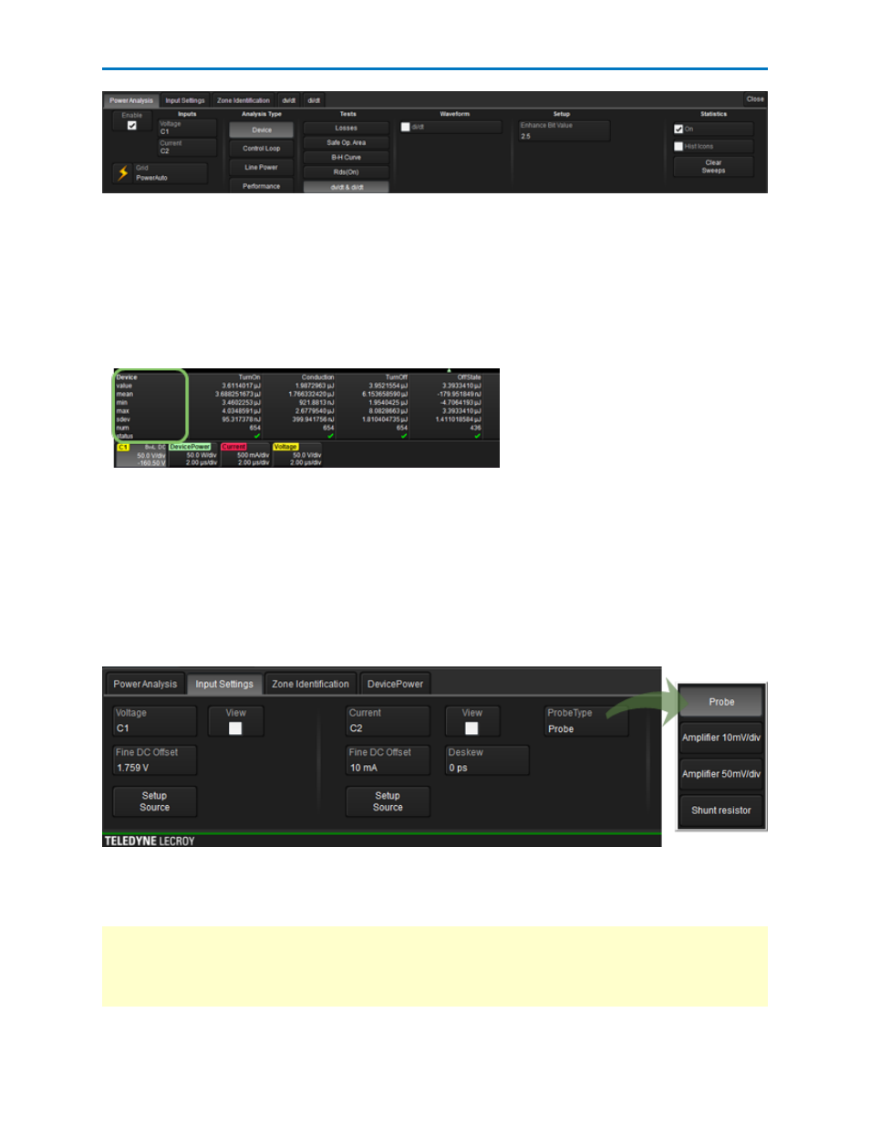
Input Settings Dialog
The second tab opens the Input Settings dialog, which allows you to adjust the Fine DC Offset and
Deskew values of your probes to increase measurement accuracy.
You can view the result of adjusting Fine DC Offset and Deskew by checking View on the Input Settings
dialog. This is a convenience to assist with fine adjustment; it's not necessary to keep this trace open.
Deskew values are duplicated on the Channel dialog, and the Power Analysis Software incorporates the
Fine DC Offset value in its measurement results.
You also use the Input Settings dialog to select the type of device used to measure current in ProbeType.
Setup Source buttons on the Input Settings dialog enable you to quickly access the source Channel
setup dialogs, where you can adjust input bandwidth limits, set up filters, AutoZero voltage probes, or
DeGauss current probes.
NOTE: When selecting Device Analysis, Losses Test and a Conduction Loss calculation method measuring
Vsat with a 2nd voltage probe, a third set of controls will become available for Deskew and DC Fine
Adjust. These controls are made available for use with a probe or amplifier solution that incorporates
voltage clamping and fast overdrive recovery, such as the DA1855A/DXC100A.
921326 Rev B
5