Teledyne LeCroy Power Analyzer Package User Manual
Page 22
Power Analysis Software
Test Circuit Setup
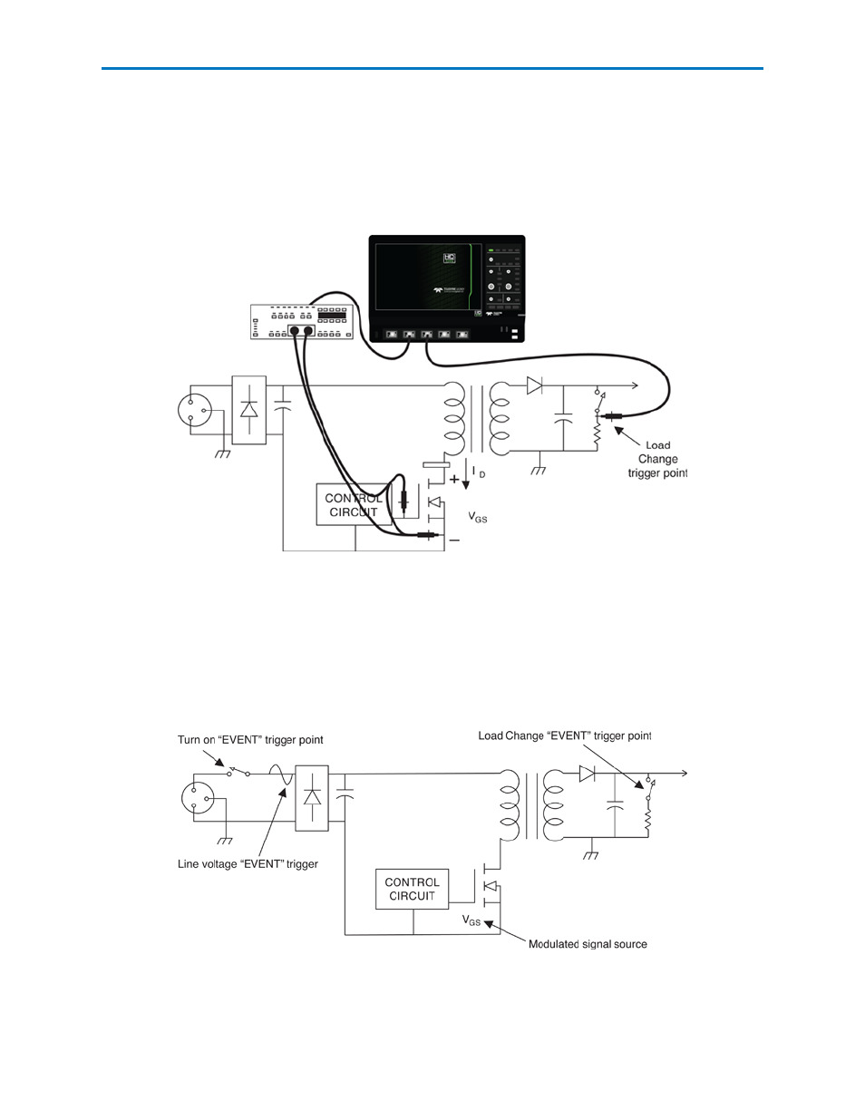
Control Loop Analysis lets you capture and analyze information contained in the power conversion cir-
cuit’s modulation. The exact setup for this measurement will differ depending on the specific circuit topo-
logy and where in the circuit under test the modulation signal is to be acquired.
Examples in this section are based on a typical setup to acquire the modulated signal at the output of a
Controller IC, as shown in the image below.
For off-line power supplies, the Teledyne LeCroy DA1855A Differential Amplifier is used to acquire the
device’s gate drive signal.
Trigger Setup
Control Loop analysis measurements usually are made to find the circuit’s response to some event.
Turn-on, turn-off, line trigger, or load change can be used to trigger the modulated signal acquisition. In
the example below, a load change on the output is used as the event trigger, and the power transistor’s
gate drive signal is used as the source of modulation information.
20
921326 Rev B
- WaveAce EasyScope Operators Manual (28 pages)
- PeRT3 Software Interface (15 pages)
- FireInspector Automation Application Programming Interface (92 pages)
- PETracer ProtoSync Software User Manual (154 pages)
- QPHY-PCIe3-Tx-Rx (32 pages)
- Signal Integrity Studio (14 pages)
- Serial Data Debug Solutions (204 pages)
- Line Code and Symbolic Decoders (20 pages)
- AORM - Advanced Optical Recording Measurements (125 pages)
- CANbus TD - Quick Reference Guide (8 pages)
- CANbus TD and CANbus TDM - Operators Manual (69 pages)
- FlexRay Trigger, Decode and Physical Layer Test (32 pages)
- MIPI D-PHY (15 pages)
- DFP2 - Digital Filter Package 2 (22 pages)
- ET-PMT - Electrical Telecom Pulse Mask Testing (11 pages)
- ENETbusD Decoder (16 pages)
- Eye Doctor II (45 pages)
- JitKit (16 pages)
- JTA2 (31 pages)
- QPHY-10GBase-KR (28 pages)
- QPHY-10GBase-T (36 pages)
- QPHY-BroadR-Reach (33 pages)
- QPHY-DDR2 (47 pages)
- QPHY-DDR3 (44 pages)
- QPHY-DDR4 (73 pages)
- QPHY-DisplayPort (19 pages)
- QPHY-ENET (78 pages)
- QPHY-HDMI (37 pages)
- QPHY-LPDDR2 (49 pages)
- QPHY-MIPI-DPHY (32 pages)
- QPHY-MOST150 (24 pages)
- QPHY-MOST50 (21 pages)
- QPHY-PCIe (30 pages)
- QPHY-PCIE3 (28 pages)
- QPHY-SAS2 (45 pages)
- QPHY-SAS3 (50 pages)
- QPHY-SATA (45 pages)
- QPHY-USB (66 pages)
- QPHY-USB3-Tx-Rx (47 pages)
- QPHY-UWB (30 pages)
- SDA II (38 pages)
- SDA III-CompleteLinQ (59 pages)
- Spectrum Analyzer (14 pages)
- USB2 Decoder (24 pages)