Power device analysis, Device analysis preliminary setup, Device analysis – Teledyne LeCroy Power Analyzer Package User Manual
Page 11
Operator's Manual
Power Device Analysis
Device Analysis Preliminary Setup
The Device Analysis tests let you make difficult measurements on devices while they operate in circuit.
The exact setup for each measurement will differ depending on what device type is to be analyzed and
where it is located in the circuit.
Test Circuit Setup
Examples in this section are based on connections to an off-line flyback power supply circuit. Meas-
urements are made on devices such as power transistors, snubber diodes, or similar devices in other
topologies.
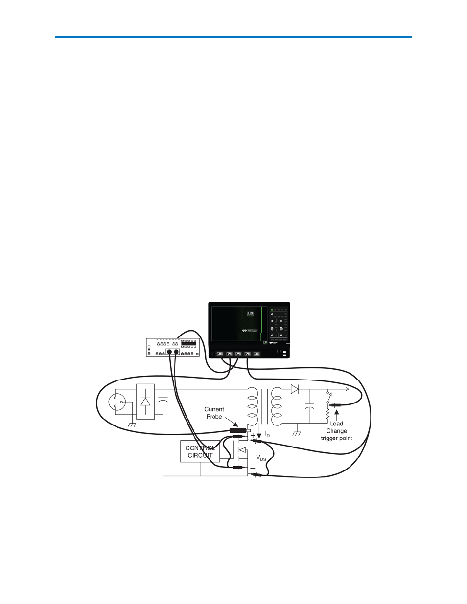
A typical setup used to analyze the power MOS-FET in an off-line switching power supply is:
l
A differential high-voltage probe is connected to Vds on the oscilloscope’s Channel 1.
l
A current probe is connected to the drain current, Id, using a current loop into Channel 2.
l
A differential amplifier, with a matched differential probe pair, is used to connect to either Vds or
Vgs into Channel 3. This amplifier will need to have voltage clamping and fast over drive recovery
in order to see the saturation voltage and have high CMRR to capture the high-side gates in an off-
line application.
The example in the figure below uses the oscilloscope’s Channel 4 to acquire a trigger signal indicating
when the load changes from maximum to minimum. You could also use the oscilloscope’s EXT trigger
input.
921326 Rev B
9