Device dynamic on-resistance test, Dynamic on-resistance test – Teledyne LeCroy Power Analyzer Package User Manual
Page 19
Operator's Manual
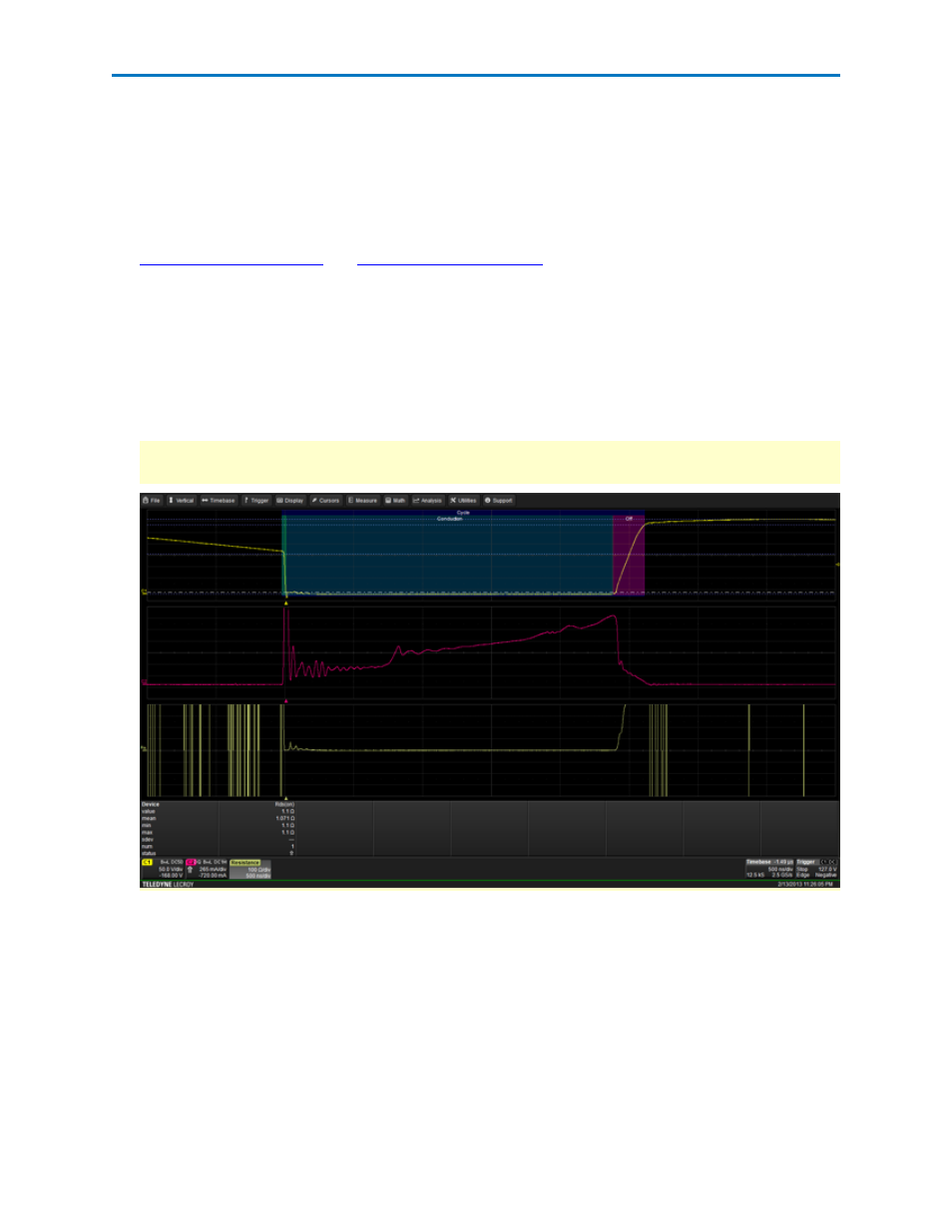
Device Dynamic On-resistance Test
This test measures the on-state resistance of a switching device. It utilizes the saturation voltage and cur-
rent measured during the on-state zone and automatically calculates the Rds(on) value, displayed in the
parameter table. For off-line power supples, it is recommended to use a differential amplifier, such as the
DA1855A and DXC100A, in order to clamp the output voltage level the oscilloscope receives when over-
driving to see saturation voltage details.
1.
and
2. On the Power Analysis tab choose Analysis Type Device and Test Rds(on).
The deskewed voltage (V) and current (I) waveforms are displayed on the first grid.
3. Adjust voltage trace Scale (V/div) and trigger Level until the voltage waveform displayed is the
device saturation voltage.
The voltage waveform is divided by the deskewed current waveform, and the resulting Resistance
waveform trace is displayed on the third grid.
NOTE: Because the device saturation voltage waveform is off screen during the non-saturation por-
tion of circuit, the math-generated resistance waveform should be ignored during this time.
4. Optionally, select Statistics to display mean, minimum and maximum values on the measurements
table. This helps to observe a consistent number.
5. Optionally, select Histicons to display a miniature histogram of the statistical measurements.
921326 Rev B
17