Closed loop test – Teledyne LeCroy Power Analyzer Package User Manual
Page 24
Power Analysis Software
Closed Loop Test
1.
.
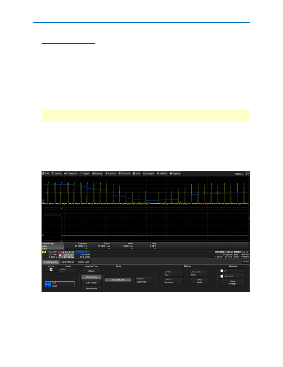
2. On the Power Analysis tab choose Analysis Type Control Loop and Test Closed Loop.
3. Choose the Operator (method) used to modulate the signal. This is the input signal parameter that
will be used to generate the Closed Loop trace.
4. Choose the Slope (Pos. or Neg.) on which to measure.
5. Touch the Level Is field and select to enter the measurement voltage Level as an Absolute Value, Per-
centage (of top to base), or one of the percent ranges.
6. Enter the absolute or percentage of voltage Level at which to measure the operator. Set this to a
level on the modulated signal where both the rising and falling edges are free of noise.
Tip: When measuring the modulation of the gate drive signal, it is best to avoid placing the level
around the pedestal.
OR
Touch the Find Level button to let the software set Level based on the amplitude of the acquired
gate signal.
The gate-drive signal is captured and displayed in the top trace. With the load change as the trigger
event, the controller's response is displayed as the blue trace in the second grid. Drag-and-drop the
Closed Loop descriptor box on any other grid to move the trace.
22
921326 Rev B