Device safe operating area test, Safe operating area test – Teledyne LeCroy Power Analyzer Package User Manual
Page 17
Operator's Manual
Device Safe Operating Area Test
This test measures that voltage, current, and power of an event all fall within safe operating levels as
defined by the device manufacturer. You can apply a mask to the power trace to help set your operating
limits or operating margin expectation for the device.
1.
and
2. On the Power Analysis tab choose Analysis Type Device and Test Safe Operating Area.
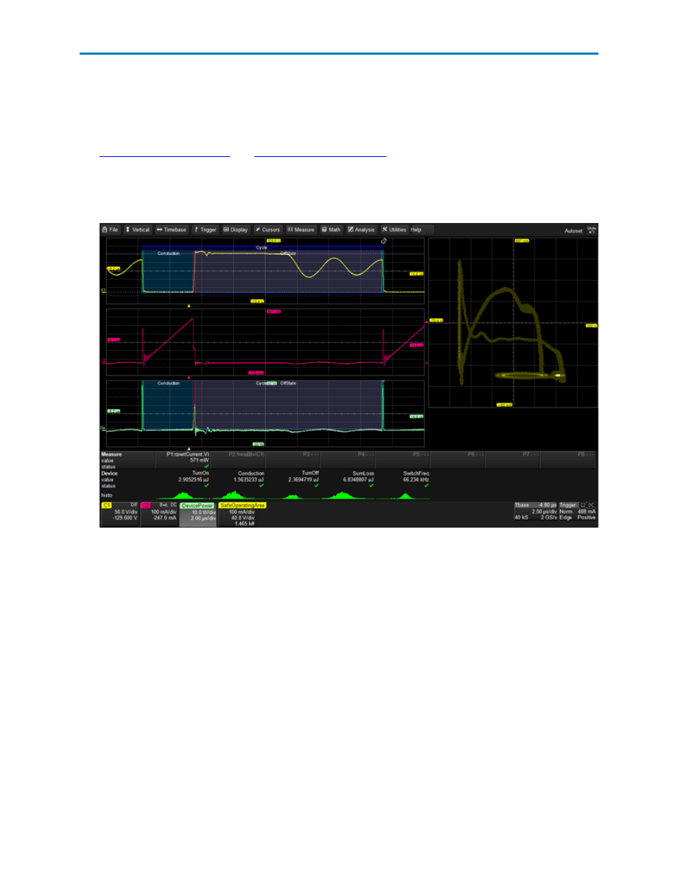
The drain-to-source voltage waveform is displayed on the first grid, and the deskewed current wave-
form is displayed on the second grid.
On the XY plot in the third grid, voltage points are plotted on the x-axis, while current is plotted on
the y-axis. Therefore, the bottom left corner of the XY trace is the 0,0 point; the top of the trace is
maximum current; far right of the trace is maximum voltage. The most frequently occurring samples
are marked by a higher intensity display.
3. To apply a mask test to the power display:
l
Check Mask Test.
l
Enter the bounds for the mask by entering the device limits defined by the manufacturer or
your desired test limits. The value represented by each grid division appears on the channel
trace descriptor boxes.
A circular red marker appears around each data point that exceeds the mask limits.
4. Optionally, select Statistics to display mean, minimum and maximum values on the measurements
table. This helps to observe a consistent number.
5. Optionally, select Histicons to display a miniature histogram of the statistical measurements.
921326 Rev B
15