Probing basics, Single-ended and differential probe basics, Differential and single-ended probe basics – Teledyne LeCroy TF-DSQ User Manual
Page 25: Tf-dsq probe calibration and deskew fixture
TF-DSQ Probe Calibration and Deskew Fixture
TF-DSQ-OM-E RevC
25
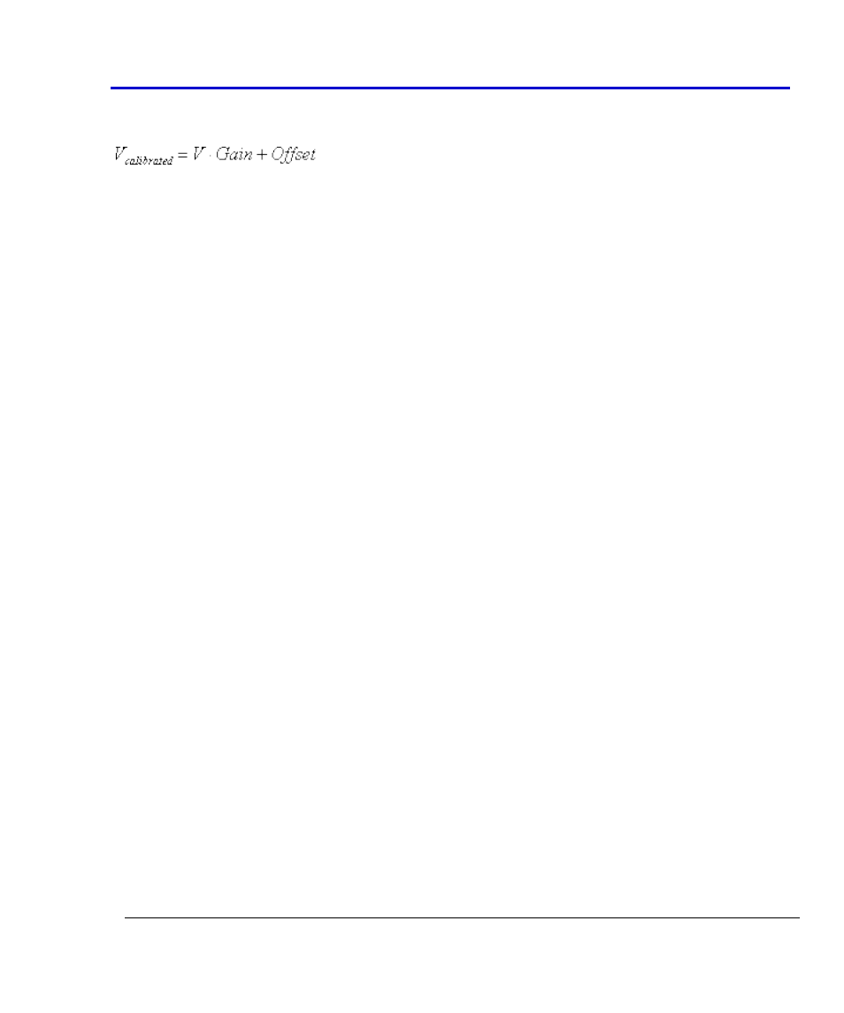
The gain and offset correction applied during DC calibration affects the voltage measured
according to the following formula:
where V is the voltage measured prior to calibration.
Probes are calibrated for each fixed gain setting of the oscilloscope, meaning they are calibrated
at 10, 20, 50, 100, 200, 500 mV and 1V per division. A unique gain and offset calculation is made
for each range.
The calibration of the probe is performed utilizing 5 DC levels. The DC levels are applied such
that the voltages ideally appear on the oscilloscope screen at -3, -1.5, 0, 1.5 and 3 vertical
divisions. The best fit line is calculated, and the appropriate gain and offset that would make the
line fit the actual voltages applied is also calculated. The gain and offset for each range is the
gain and offset correction displayed in the gain and offset fields.
In all cases, the DC levels applied to the probe are measured by an ADC on the fixture placed
near the probing points. In this way, the absolute voltage at the probe tips is precisely known
and any DC probe loading effects are taken into account.
In the case of single-ended probes, the DC levels applied to the V+ probing pad are the same as
the voltages that appear at the appropriate grid locations on the oscilloscope screen.
Differential probes are handled slightly different. In their case, the voltage applied to the V+ tip
is the voltage specified in the Common mode voltage field, plus half the voltage desired on the
oscilloscope screen. The voltage applied to the V- tip is the common mode voltage minus half
the voltage desired. In this way, the probe experiences the specified common mode voltage,
and the differential voltage measured by the probe is calibrated for common mode voltage
effects.
Probing Basics
Single-Ended and Differential Probe Basics
Single-Ended and Differential probe discussions are a sometimes confusing subject. There are
aspects of operation that must be known in order to understand their calibration.
Single-Ended
A single-ended probe exposes a probing tip and a ground connection lead. Typically, the ground
lead is connected to the outer conductor in a coaxial cable, which is connected directly to the
oscilloscope's ground. The probing point is typically connected to the center conductor.
Typically, the ground connection represents an essentially zero-ohm connection to oscilloscope
ground, and the probe tip is a specified impedance to that ground. Other than probes, a 50-ohm
cable is often used for single-ended measurements.