Dc calibration theory, Dc calibration, Probe dc calibration – Teledyne LeCroy TF-DSQ User Manual
Page 24: Operator's manual
Operator's Manual
24
TF-DSQ-OM-E RevC
The TF-DSQ fixture, in accordance with the philosophy of requiring only one calibration in the
fixture, handles this in a special manner. The user simply enters the measured risetime of the
signals after the probe is connected to the circuit. Since the oscilloscope software saves the
edge acquired during the deskew calibration process, it applies this saved edge to a variable
filter using digital signal processing until the measured risetime is achieved. At that point, the
software calculates the difference in the time of the 50% crossing and calculates an additional
skew correction to be applied. In this manner, the risetime is compensated for in the deskew
calibration without the requirement of re-calibrating.
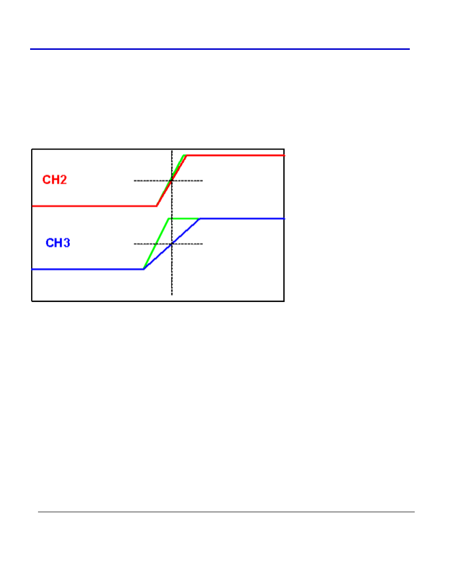
The previous figure shows the traces realigned as a result of the skew correction applied after
the measured risetime has been entered.
DC Calibration Theory
DC calibration involves the calculation of two constants to be applied to waveforms to correct
for voltage measurement inaccuracy. The two constants are the gain (applied multiplicatively)
and the offset ( applied additively). It is important to distinguish the gain and offset correction
from the channel gain determined by the sensitivity control (volts/division selection) or the
offset control. The sensitivity and offset controls change the absolute gain and offset of the
front end amplifier, but cannot correct for inaccuracy. This is also true with the vertical gain and
offset controls in zooms. The way to visualize this is to place a cursor at a point on a waveform
and read the voltage. Adjusting volts/div or offset, or adjusting the gain or offset of a zoom,
affects the size of the waveform on the screen, but does not affect the voltage measured at the
cursor position.