Tf-dsq probe calibration and deskew fixture – Teledyne LeCroy TF-DSQ User Manual
Page 21
TF-DSQ Probe Calibration and Deskew Fixture
TF-DSQ-OM-E RevC
21
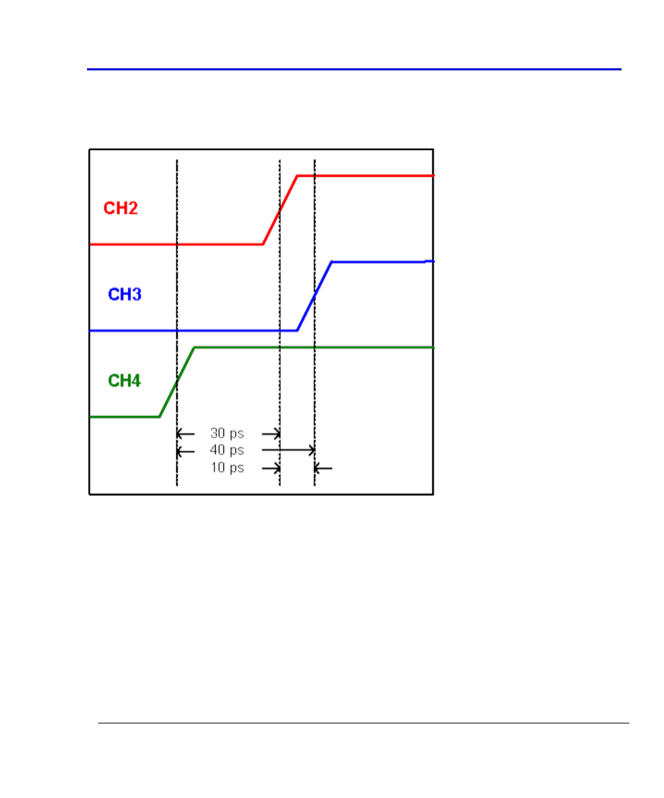
The following example illustrates this scenario:
Two probes are used in a system. They are connected to channels 2 and 3. The TF-DSQ fixture is
connected to channel 4. When the oscilloscope is triggered on channel 4, you observe the
following edges:
When the probes are deskewed, the relative time between channel 4 (where the TF-DSQ fixture
is connected) and channel 2 is calculated as 30 ps, and -30 ps and is entered in channel two's
skew entry. Similarly, the time between channel 4 and channel 3 is calculated as 40 ps and -40
ps is entered in channel 4's skew entry. When triggering on channel 4, channel 2 is advanced 30
ps in time and channel 3 is advanced 40 ps in time such that all of the edges are aligned with
each other and with the trigger point.
When triggering on channel 2, these times are adjusted by a common 30 ps. So, 30 ps is added
to channel 2 to cause 0 deskew amount, and 30 ps is added to channel 4 to cause -10 ps deskew.
Without this common addition (or delay) of all waveforms by 30 ps, all edges would remain
aligned, but channel 2's trigger position would be off by 30 ps. This explains how the 30 ps
(commonly added to all waveforms) keeps the trigger points aligned.