Deskew risetime adjustment theory, Risetime correction, Operator's manual – Teledyne LeCroy TF-DSQ User Manual
Page 22
Operator's Manual
22
TF-DSQ-OM-E RevC
Deskew Risetime Adjustment Theory
Two scenarios require adjustment of the deskew values to account for risetime:
1. Two probes are used for relative time measurements, but each probe has a different
risetime.
2. Two probes are used for relative time measurements, but each signal has a different
risetime.
The first case is explained here with obvious analogy to the second case.
Two probes are often utilized for measurements where each probe has a different risetime. This
may occur because you are making a measurement where a reasonably low bandwidth probe
can be used, but you do not have two of same probe, so you end up using a second one with a
higher speed than the first.
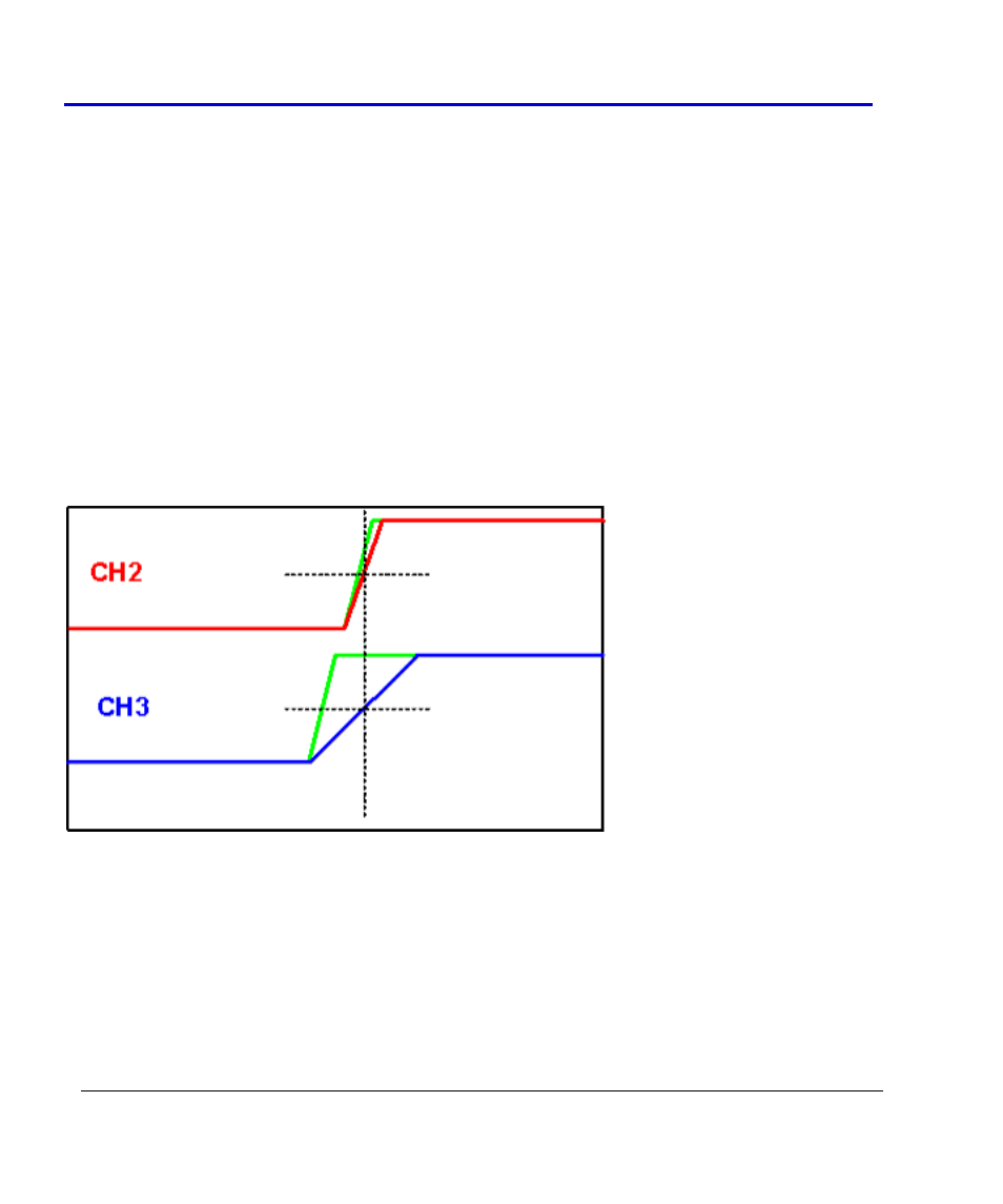
When the probes are deskewed, the high-speed edge from the TF-DSQ fixture is utilized. The
deskewed probes might show signals that look like the following when the high-speed edge
supplied by the TF-DSQ fixture is observed:
In the previous picture, the green trace edge is the one actually supplied by the TF-DSQ fixture.
However, because of risetime limitations of the probe and channel, the edges appear as the red
and blue traces. These traces are shown aligned at the 50% crossing point at the end of the
deskew calibration.