Operation – Teledyne LeCroy PXD222 User Manual
Page 29
Operation
PXD222-OM-E Rev A
ISSUED: November 2001
25
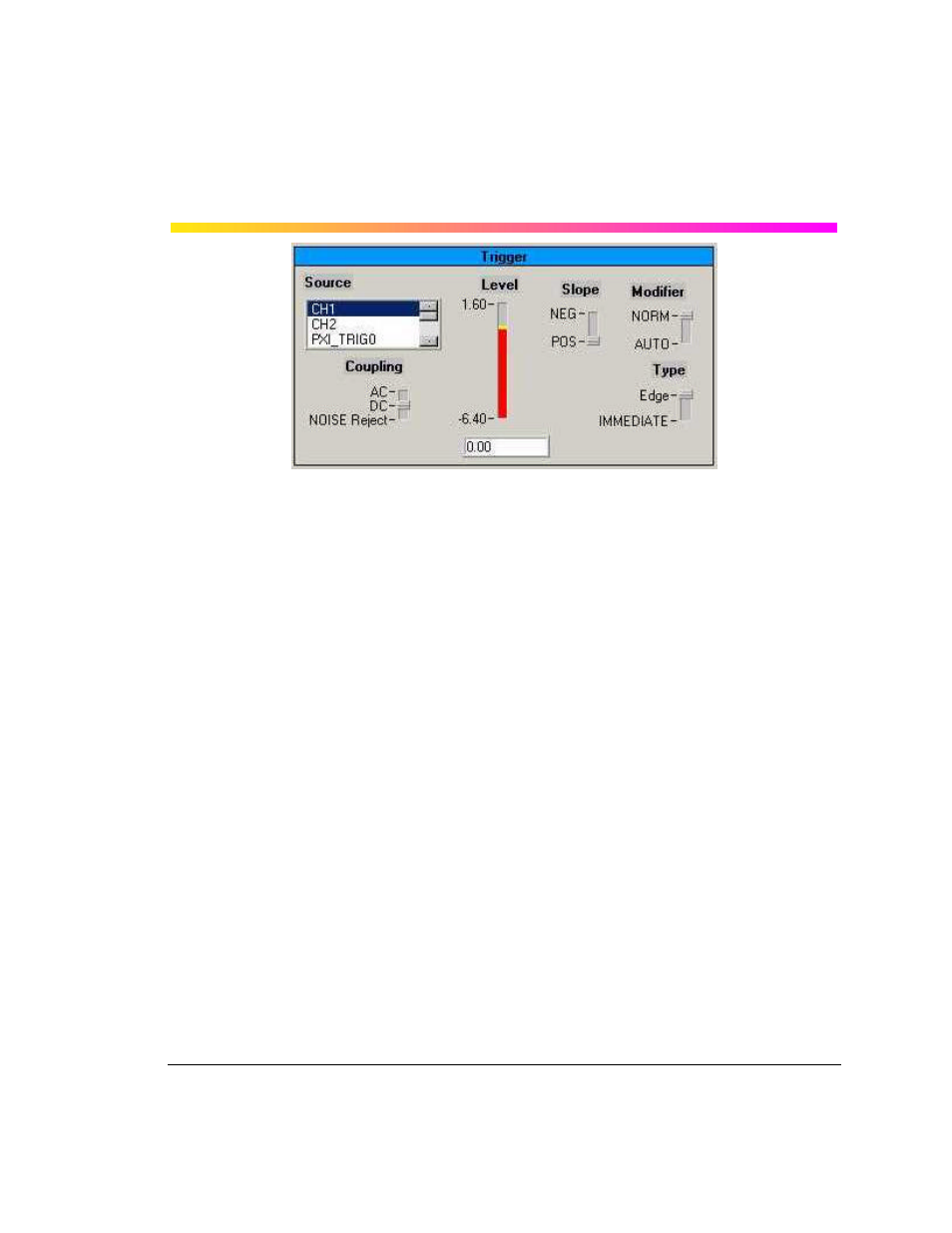
Source: The trigger source for the digitizer may be either of the input channels or the PXI Trigger
and Star Trigger lines on the PXI backplane.
Coupling: This sets the trigger coupling for the input channels. DC is used when all the signal fre-
quency components are coupled to the trigger circuit. When AC is selected the signal is capaci-
tively coupled, DC levels are rejected, and frequencies below 50 Hz are attenuated. NOISE Reject
is a filter that will help reduce jitter when triggering on noisy waveforms.
Level: Defines the source voltage at which the trigger circuit will generate an event.
Slope: Determines the direction of the trigger voltage transition used to generate a particular trig-
ger event.
Modifier: In NORM mode the digitizer will acquire while there is a valid trigger. In AUTO mode the
trace will automatically be displayed regardless of a valid trigger. When a valid trigger is present in
auto mode, the digitizer will behave as if in normal mode.
Type: Edge type requires a valid trigger edge. IMMEDIATE type will force a trigger even if the trig-
ger conditions are not met.
On/off: turns datalogging on and off.
Directory: Sets the directory for storying waveforms. Entering a period sets the current directory
of the Quick-Start Demo; entering another value (e.g., "Test 1") creates a new folder called "Test1"
referenced from the current directory.
Filename: Sets prefix for filename.
Index: An auto-incrementing index is appended to the above filename. When the datalogger is
turned on, and the program is in continuous Acquisition mode, each waveform will be stored.