Interface settings – Teledyne LeCroy Zi Oscilloscope Synchronization ProBus Module (Zi-8CH-SYNCH) User Manual
Page 5
Instructions
918246‐00‐RevA
5
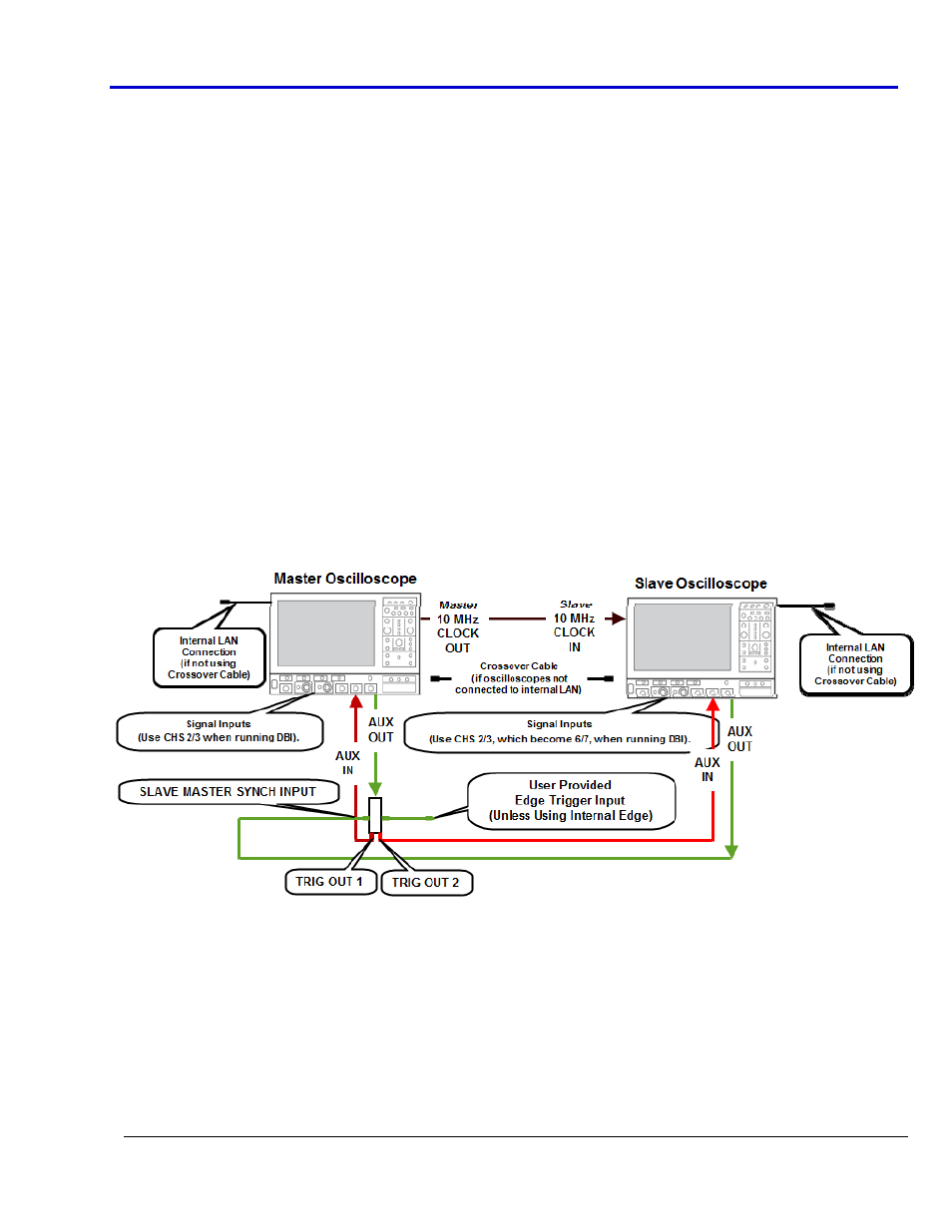
6. Now, make signal input connections as desired.
• If providing your own Edge Trigger Input signal, connect it to the USER TRIGGER INPUT connector on the
Zi‐8CH‐SYNCH module.
• Otherwise, use the module’s Periodic (fixed frequency clock) mode from the Trigger 8CH‐Synch dialog on
the Master oscilloscope's user interface. See Interface Settings (on page 8) for more information.
PLEASE NOTE THE FOLLOWING:
• When making connection 3 and 4 previously described, be sure to use the 36" SMA cables provided as
they are a reasonable, matched length.
• You can achieve up to eight 4‐16 GHz oscilloscope channels from two different WaveMaster 8 Zi
oscilloscopes, or four 20‐30 GHz channels from two different WaveMaster 820, 825, or 830 Zi
oscilloscopes.
• When running four 20‐30 GHz channels from two different WaveMaster 820, 825, or 830 Zi oscilloscopes,
both instruments must be setup in DBI mode (click the Timebase trace descriptor label and enable DBI
from the dialog).
• The four channels used when running in DBI mode are 2 and 3 (from the Master) and 6 and 7
(renumbered from the Slave).
• Ensure the most accurate readings by repeatedly using your cable setup in the same specific
configuration. Once you've setup your cables, you must then deskew all the Master and Slave
oscilloscopes signal input channel connections (6, previous) you plan on using. See Deskewing Master
and Slave Channels (on page 9) for more information.
When the module is properly connected to the oscilloscopes, the entire setup should look like the following.
Interface Settings
Remote Slave DSO Dialog
1. Using the master oscilloscope's interface, connect from the master to the slave from the Remote Slave
DSO dialog (Vertical → Remote Slave from the menu bar).