Zi oscilloscope synchronization module 10 – Teledyne LeCroy Zi Oscilloscope Synchronization ProBus Module (Zi-8CH-SYNCH) User Manual
Page 10
Zi Oscilloscope Synchronization Module
10
918246‐00‐RevA
2. Connect one 36" SMA cable to the SMA power splitter (provided) and to whatever fast edge signal is
being used for deskew. Then, connect a cable being used for actual measurements to C2 of the Master
and another to C2 (or 6) of the Slave oscilloscope, and then connect the other ends of these cables to the
SMA splitter. If probes are being used for measurement, the PCF‐200 Probe Deskew Fixture may be used
instead of cables.
Note: Deskew adjustment for each channel must be done from the oscilloscope (Master or Slave) where
they are physically input.
3. Ensure that both channels are displayed properly on the Master oscilloscope display grid, and that the
v/div and other setting of both channels are as they will be when making actual measurements.
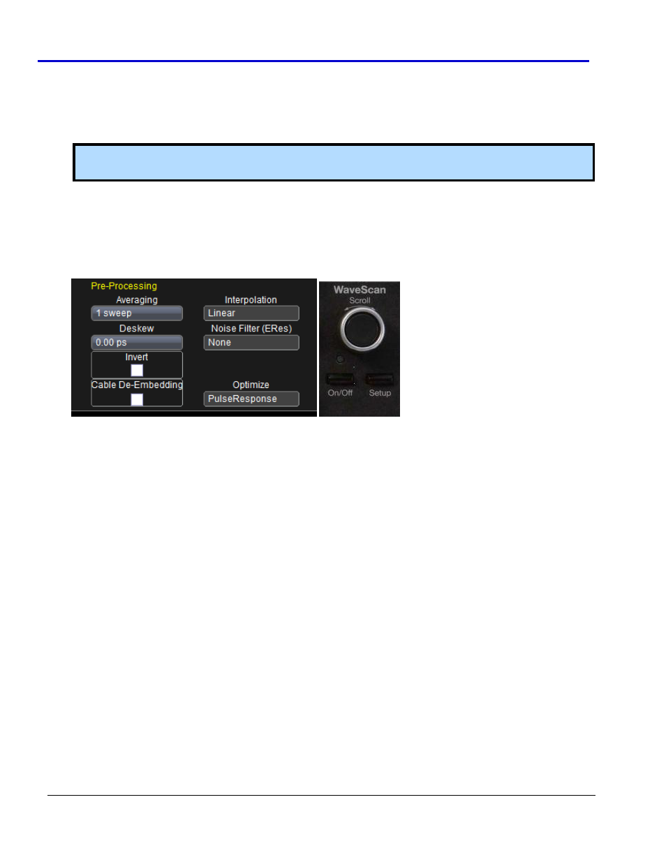
4. Now, to precisely align the edges of both signals, open the C2 channel dialog in the Master oscilloscope,
touch the deskew area once and deskew the signal using the Pre‐Processing Deskew adjustment. You can
use the slider bar, type in a value, or use the WaveScan front panel button (which doubles as an
"Adjust" button when the Deskew field is highlighted in yellow).
Adjust the deskew until both the C2 (Master) and C2 (relabeled C6, Slave) are edge‐aligned.
• When using the Zi‐8CH‐SYNCH in User Edge trigger mode, you must input an edge signal for the
deskew to the module. This allows you to deskew one channel at a time ‐ unless a second power
splitter is used, creating a second input for a second channel.