Teledyne LeCroy Zi Oscilloscope Synchronization ProBus Module (Zi-8CH-SYNCH) User Manual
Page 2
Zi Oscilloscope Synchronization Module
2
918246‐00‐RevA
The user interface for common triggering and display of channels is enabled on the Master oscilloscope when
the Zi‐8CH‐SYNCH hardware ProBus module is attached to the Master AUX OUT connector. All triggering is
performed by the Zi‐8CH‐SYNCH module; data transfer is via an Ethernet crossover cable connected to the
Master and Slave Ethernet ports, or through a network connection. Handshaking between oscilloscopes is
automatic once the IP address of the Slave oscilloscope is defined.
Connections
The general setup involves the following:
• The Zi‐8CH‐SYNCH module is connected to the AUX OUT ProBus connector on the Master oscilloscope.
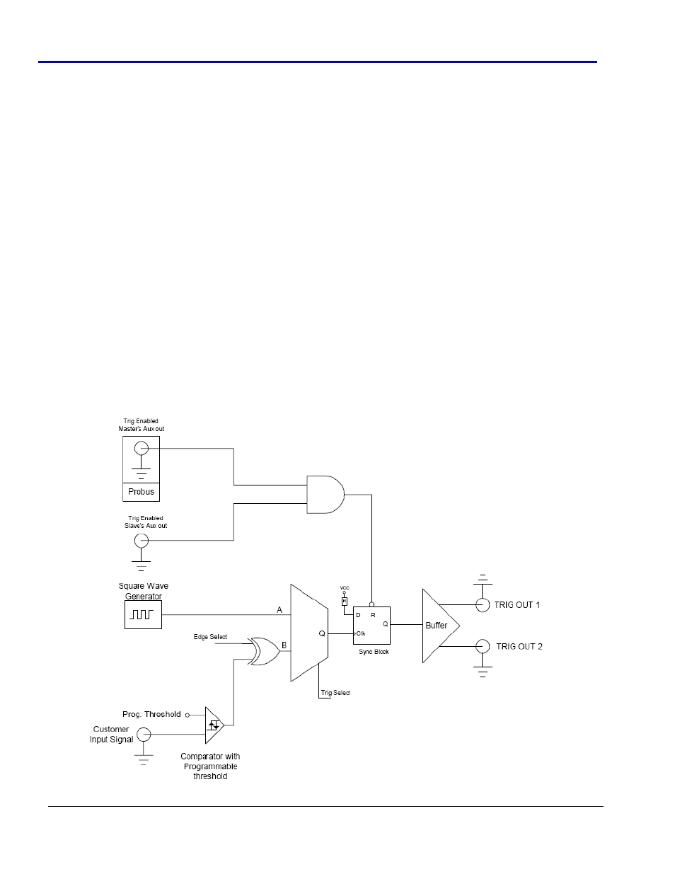
• The module contains a comparator with a programmable threshold and a buffer to accept an external
customer trigger signal (in User Edge trigger mode) with a relatively slow rise time and outputs two
identical trigger signals (TRIGOUT1 and TRIGOUT2) with ~100 ps rise time to the Master and Slave
oscilloscopes AUX IN ProBus connectors. These connections serve as their corresponding synchronized
trigger inputs. If no external customer trigger signal is available, the module can be self‐triggered in a
Periodic trigger mode.
• Finally, the SLAVE‐MASTER SYNCH connection is made from the Slave AUX OUT to the module.
The SLAVE‐MASTER SYNCH connection provides positive feedback from the Slave to the Zi‐8CH‐SYNCH
module that an acquisition has occurred on the Slave (ensuring Master + Slave acquisition integrity). This
is provided via a TRIG ENABLED output signal from the Slave oscilloscope. The 10 MHz Reference Clock
Out on the Master oscilloscope is connected to the 10 MHz Reference Clock In on the Slave oscilloscope
in order to synchronize the two oscilloscope acquisitions. Upon proper connection and receipt of a valid
TRIG IN signal, the Master and Slave oscilloscope simultaneously acquire data.