APC Silcon DP300E Series User Manual
Page 14
14
User Guide Silcon DP300E Series 480V 400-500kVA
7OA0004 US rev. 02
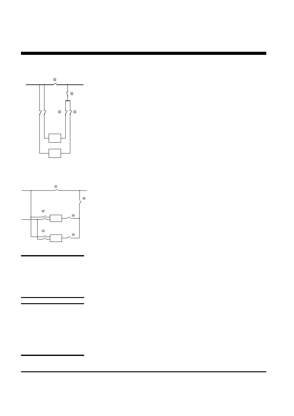
DP300E
DP300E
Q010a
Q001a
Q002a
Q004
Q010b
Q001b
Q002b
Utility 1
Q003
Service bypass switch
H003
Load
Utility 2
H004
H002b
H002a
H010a
H010b
Single Utility
Dual Utility
2.5.3
Isolating one UPS for service/maintenance
In a redundant system one UPS can be isolated for service/maintenance without
affecting the other parallel UPS(s).
1.
Check that the remaining UPS(s) will be able to carry the load when one UPS is
isolated.
2.
Switch off the system to be isolated for maintenance by pushing the red “OFF”
push-button.
3.
Disconnect output and utility by turning output switch (Q002) to position “0”
and input switch (Q001) to position “0”, disconnect battery by opening battery
MCCB.
If dual utility is present, turn the bypass input switch (Q010) to position “0”.
Switching back the UPS to normal parallel/redundant operation
1.
Turn the input switch (Q001) and the output switch (Q002) to position “1”.
If dual utility is present, turn the bypass input switch (Q010) to position “1”.
2.
Charge capacitors, connect battery and start up the UPS as described in
chapter 2.5.
The UPS will automatically switch to normal operation and start load sharing
with the other parallelled UPS(s).
Stop, Start & Operating the External Service Bypass Panel
WARNING!
The system will discharge built-
in capacitors. However, before
working on the system check
with a multimeter that there is
no dangerous voltage on the
terminals.
DP300E
DP300E
Q003
Service
bypass
switch
H003
Q001a
Q001b
Q002b
Q004
Q002a
Load
Utility
H004
H002a
H002b
NOTE:
When Q002 is in position “0”
the UPS can be operated and
tested as a single system
without affecting the other
parallel UPS(s) if proper
monitoring has been installed.
Available on all APC bypass
panels.