KB Electronics KBVF-48 User Manual
Page 23
12.1 POWER ON (PWR) – The “PWR” LED will illuminate green when the AC line is applied to the drive.
12.2 STATUS LED (ST) – The “ST” LED is a tricolor LED which provides indication of a fault or abnormal
condition. The information provided can be used to diagnose an installation problem such as incorrect
input voltage, overload condition, and drive output miswiring. It also provides a signal which informs
the user that all drive and microcontroller operating parameters are normal. Table 6, on page 22,
summarizes the “ST” LED functions.
Note: The drive is factory set to the Automatic Start Mode. For Manual Start/Reset, see Section 9.6,
on page 20.
13 TRIMPOT ADJUSTMENTS
The drive contains trimpots which are factory set for most applica-
tions. See Figure 5, on page 13, for the location of the trimpots
and their approximate factory calibrated positions. Some applica-
tions may require readjustment of the trimpots in order to tailor the
drive for a specific requirement. The trimpots may be
readjusted as described below.
WARNING! If possible, do not adjust trimpots with
the main power applied. If adjustments are made
with the main power applied, an insulated adjustment tool
must be used and safety glasses must be worn. High voltage
exists in this drive. Fire and/or electrocution can result if caution is
not exercised. Safety Warning, on pages 8 and 9, must be read and
understood before proceeding.
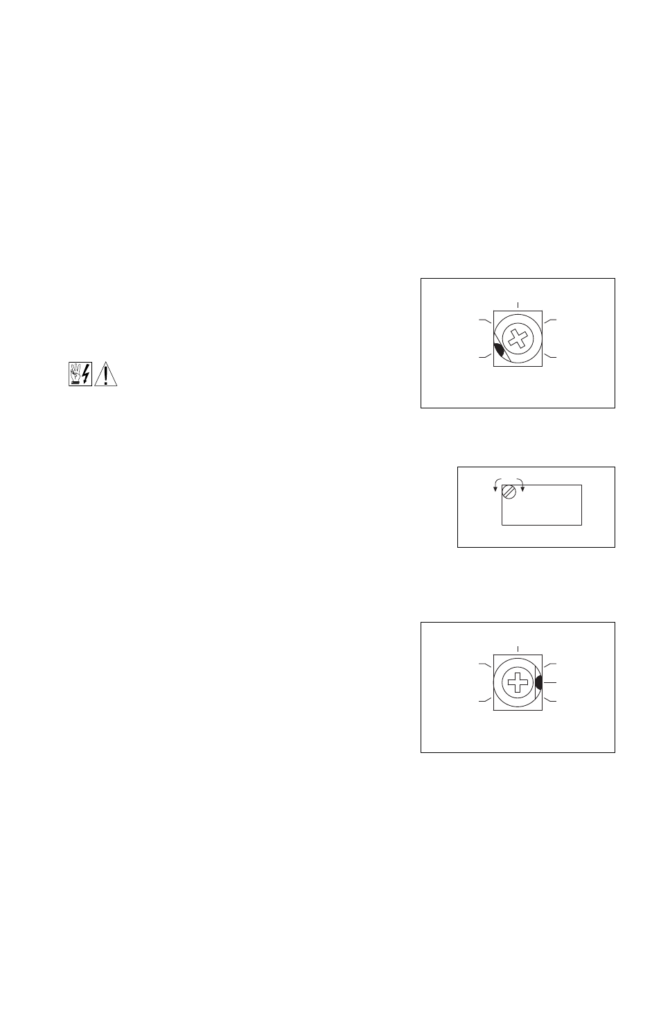
13.1 MINIMUM SPEED (MIN / OFFSET) – Sets the minimum speed of
the motor.
13.1.1 Models KBVF-27, 29 – The MIN Trimpot is factory set to
0% of frequency setting. For a
higher minimum speed setting, rotate the MIN
Trimpot clockwise. See Figure 28.
13.1.2 Models KBVF-45, 48 – The OFFSET Trimpot on the
SIVFR is a 10-turn trimpot which allows for accurate
setting of the minimum speed of the motor. The
OFFSET Trimpot is factory set to 0% of frequency
setting. For a higher minimum speed setting, rotate
the OFFSET Trimpot clockwise. See Figure 29.
Note: The MIN Trimpot on Models KBVF-45, 48 is
not functional.
13.2 MAXIMUM SPEED (MAX) – Sets the maximum speed
of the motor.
13.2.1 Models KBVF-27, 29 – The MAX Trimpot is factory
set to 100% of frequency setting. For a higher
maximum speed setting, rotate the MAX Trimpot clockwise. For a lower maximum speed set-
ting, rotate the MAX Trimpot counterclockwise. See Figure 30.
13.2.2 Models KBVF-45, 48 – The MAX Trimpot on the SIVFR is a 10-turn trimpot which allows for
accurate setting of the maximum speed of the motor. The MAX trimpot is factory set to 100%
of frequency setting. For a higher maximum speed setting, rotate the MAX Trimpot clockwise.
For a lower maximum speed setting, rotate the MAX Trimpot counterclockwise. See Figure 31,
23
30
MIN
(Shown Factory Set to 0% Frequency Setting)
0
15
40
35
FIGURE 28 – MINIMUM SPEED
TRIMPOT RANGE
MODELS KBVF-27, 29
80
(Shown Factory Set to 100% Frequency Setting)
MAX
70
75
100
110
90
FIGURE 30 – MAXIMUM SPEED
TRIMPOT RANGE
MODELS KBVF-27, 29
OFFSET
-
+
ADJUST
FIGURE 29 – OFFSET TRIMPOT
MODELS KBVF-45, 48